Marine Lightning Protection Inc.Being at the forefront of both the basic science and product development in this area, we are uniquely qualified to address all of the problems inherent in lightning protection on the water. Whether for a fiberglass jet ski or a superyacht our method is the same - to place lightning conductors on the outside of the vessel with multiple air terminals at the top and multiple grounding terminals at the waterline. This provides a shielding enclosure, external current pathways, and more effective grounding to the water surface. We can also address lightning issues with metal-hulled vessels ranging from jon boats to supertankers, and can give advice on electronics protection by considering wire routing, shielding and surge suppression. |
||||
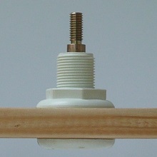
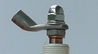
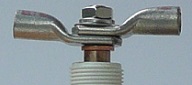
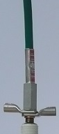
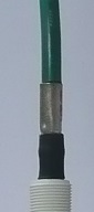
Ship systemsThe desirable features of a ship lightning protection system cover a broad range from personal safety of passengers, surge protection of electronics, protection of vulnerable instruments or structures, lowered downtime to repair lightning damage, safety procedures for loading explosive materials, etc. Over the years we have had many enquiries from ship agents who have been interested in addressing lightning protection and are very familiar with both the type of damage to be expected and the techniques needed to address any problem that might be encountered. While the priorities for each lightning protection project vary from ship to ship, one common feature for all projects is that in a task of this size an appropriate amount of analysis is required in order to assess the best course of action. In order to expedite this we recommend our consulting services so that we can give the matter the attention it deserves.Given the wide range of potential issues with lightning protection of ships, it is not surprising that a common problem is that the agent does not understand how to define the most pressing concern. Ill defined Class regulations, use of ambiguous terms such as "lightning arrestor", and the widespread availability of devices with checkered histories do not help. To this end we offer a standard 20-hour consulting package that provides basic concepts, identifies prioritized issues, and develops the framework for an effective lightning protective process. Please email us with questions or details. ProductsNew SiedarcTM features single component silicon bronze electrodeThe 3/8-16 stud on the connecting end of the solid silicon bronze electrode provides flexibility for many different types of connections, as shown in the photos below. The absence of any plating on these electrodes means that tips can be sanded without causing galvanic problems if fairing into the hull surface is desired. Price for the basic electrode shown on the left is $150, plus $30 for faired tip. Prices for other connection options vary. The option that we recommend for a single termination is the perpendicular connection shown on the right. This option comes with a 2 AWG splice crimped onto the connecting stud and is priced at $195, plus $30 for a faired tip. Cable is not included.
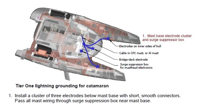
     Electronics protectionSince a lightning protection system is intended to protect the hull and occupants, electronics is still vulnerable. Even in metal-hulled vessels damage to electronics systems is pervasive. We are now addressing this issue and can supply both parts and advice to minimize the risk. As an example, consider the following three tiers of protection that we recommend for catamarans: even in the Tier 1 system we include surge suppression on all wiring exiting the mast.Three tier systems for catamaransTier 1: Mast base grounding and mast systems surge protection
Tier 2: Add immersed ground studs aft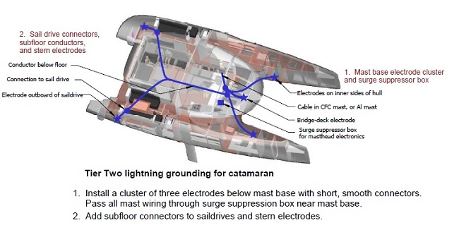
Tier 3: Add loop conductor and bow & stern electrodes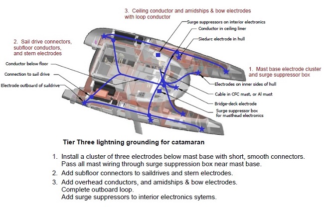
Air terminals for carbon mastsSince CFC is a conductor, but not a good one, it is difficult to deal with when designing a lightning protection system. Since we have not been able to design and test a reliable air terminal support for CFC masts, unfortunately we can no longer offer advice or devices for protection for them. Carbon fiber rigging is also a risk factor that we can do little about.Air terminals for metal vesselsEnveloping the interior with a conducting steel or aluminum hull still leaves all topsides transducers vulnerable. We deal with each metal vessel on a customized basis to identify the major vulnerabilities and then develop appropriate techniques and hardware to lower the risks of direct lightning attachment, formation of upward streamers, and damage from voltage surges on cables.Silicon bronze grounding productsSince current flow during lightning strikes appears to be via sparks, even below the waterline, we have developed the GStud ($200 each) , a silicon bronze immersed grounding electrode suitable for additional grounding near bow thrusters, hull transducers, keel-stepped masts, etc. Since these are embedded in a Marelon through-hull they are ideal for CFC hulls. Another product that now is available in silicon bronze is our SiedarcTM electrode in either a mushroom (SE-M-SiBr) or flush through-hull (SE-F-SiBr) @ $150. Add $30 for fairing.Mechanism for SiedarcTM electrodesCharge on water surfaceA recent report from one of our customers has shed some light on how our electrodes function - by forming sparks just above the water surface that neutralize the ground charge residing on the surface. See the discussion and animation on our Science page, or click here for a preview.Latest statisticsBad News for CatamaransBoat US has released their latest statistics for lightning claims. These show that not only are there twice the frequency of multihull claims, compared with monohulls, but also the average claim is 67% higher. See all the statistics here. Also, we explain the higher strike frequency for catamarans in terms of their wider footprint. This leads us to conclude that you can increase your risk by 5-10 times when you anchor out, even if you are in a monohull!New standard - NFPA 780-2017Protect a boat Like a buildingThe October 2007 edition of Boat US's Exchange explains this novel concept. See the article here. This concept has been incorporated into the National Fire Protection Association Lightning Protection Standard NFPA780-2011, and later versions, that are now available. The watercraft section is Chapter 10 in the new (2011) version. Derivations for the new formulae regarding the use of metallic fittings in the system are published here. Also read Vincent Daniello's interpretation in the May 2009 edition of MotorBoating.ProjectsSee our Systems Gallery for pictures and descriptions of systems on all types of power and sail boats. | ||||
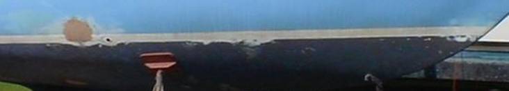
PrinciplesPeer-reviewed science forms the basisOur approach to lightning protection is based solidly on observation and scientific theory. The foundation was established in a paper published in 1991 in the prestigious IEEE Transactions of Electromagnetic Compatibility. As a result of this paper, subsequent renditions of standards published by ABYC and NFPA upgraded their recommended sizes for down conductors from #8AWG to #4AWG and noted that a ground strip is a more effective grounding conductor than a square plate of the same area.Another fundamental problem revealed in this scientific work was that a one square foot ground plate is "hopelessly inadequate" to prevent sideflashes in fresh water.This was not addressed in these earlier standard rewrites since, at the time, there was no obvious solution. We can now solve this problem with our patented SiedarcTM electrodes that, when distributed around the hull, provide the multiple exit points needed for effective grounding. More recently, we have worked with the NFPA 780 technical committee to establish a new standard based on these new ideas, that is now published as Chapter 8 in the 2008 version of NFPA 780 This standard is based on the simple concept that a boat should be protected the same as a building, with the lightning conductors on the outside rather than through the middle of the boat. As the ground attachment path for a 5-mile long spark carrying tens of kiloamperes, the protection system has the task of safely diverting this current around crew, sensitive electronics, and hull components. However, even when the current is flowing in the water, voltage differences can cause sideflashes, both inside the boat and between the boat and the water. These present a shock hazard to the crew, produce overvoltage in electronics systems, and can blast holes through the hull. Management of the sideflash problem is the fundamental issue in the design of an effective marine lightning protection system. Grounding Concepts page for a technical explanation of the underlying concepts and suggestions as to how these can be applied to a protection system. Sideflash management is the objectiveAn interesting feature of hull damage is the tendency for sideflashes to form around about the waterline. Apparently either the water surface or the waterline itself causes charges to accumulate, usually on internal conducting fittings, and initiate sparks through the hull. The effect is more pronounced in fresh water than salt. In
lightning protection circles, the conventional solution to a problem such
as this is to add conductors where the damage is observed.In the above case this means placing
lightning conductors through the hull at the waterline. Since it is impractical to install
multiple ground plates in a hull, we developed the SiedarcTM electrode to provide the necessary exit terminals. This is effectively an air terminal near
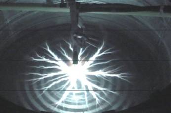
the water.In fact, each In order to investigate the effectiveness of this concept, we tested an electrode with a 10kV generator for both salt and fresh water at Kennick Inc. in St. Petersburg. Even though 10kV is much lower than what would be expected during a lightning strike, we obtained results that clearly indicated the promising potential for the method and further elucidated the best mode of operation. Specifically, in the photo below, with the electrode about 1/4" above the surface of salt water, a spark of about 15" in diameter was produced. Clearly the sparking is contained very close to the water surface, perhaps even above it, showing the importance of the surface for current dissipation. In fresh water, the spark connected all the way to the sides of the container, about 12" away. In contrast, when the electrode tip was immersed just below the water surface, a small (~1/2") glow was observed but no sparks. The conclusion is that an electrode can generate a spark that is orders of magnitude longer than the spark gap in air when placed above the water surface. Hence the optimum placement is just above the water surface. The animation below illustrates how we expect the SiedarcTM electrodes to function. See our Science page for more details 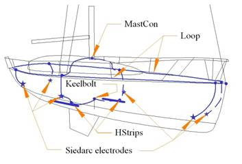
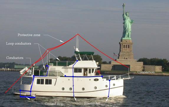
Providing exit terminals around the perimeter of the hull is the key to an effective system design since, in addition to dispersing the current more uniformly around the boat, it also enables the lightning down conductors to be routed externally to all wiring and conducting fittings. This is illustrated for a sailboat on the right. The lightning conductor from mast base connects to both the chain plate and the loop before passing down to a daisy-chain SiedarcTM electrode just above the waterline, and from there via an immersed HStripTM to a keel bolt (and base of a keel-stepped mast). SiedarcTM electrodes at bow and stern provide more exit terminals from the loop to the water. This geometry is mirrored on the port side, as indicated by the dashed lines. That is, there is a total of two HStrips and six SiedarcTM electrodes. Thus a conducting grid covers the interior of the boat and a total of eight exit terminals are distributed over the hull near the waterline. For a keel-stepped mast, make another connection from the mast base to both the keel bolt and the HStrips. Guiding the current on the outside rather than through the middle of the boat minimizes shock risk and emi. In addition, a bonding loop around the boat at about deck level equalizes potentials, provides additional paths for current flow, and can be used for bonding conducting fittings. In a major departure from the status quo, NFPA (the National Fire Protection Association) has recently revised their watercraft standard (NFPA 780 Ch.8) to include the concepts of a loop conductor, external down conductors, and perimeter grounding electrodes. See our Standards page for details. With this new system the conductor layout more closely mirrors that found on the typical lightning protection system on a building. We call this system of external lightning conductors and peripheral exit terminals the ExoTerminalTM protection system. In the photo below, we have shown where additional (internal) lightning conductors, grounding terminals, and air terminals were installed to fabricate this type of system. Products & servicesWe can provide all of the components needed in a marine lightning protection system - air terminals, connections, grounding strips and SiedarcTM electrodes. See our Products page for details.We also offer consulting services for:
Contact
Please email if you have any questions.
Page hits
| ||||
 one is designed to the same specification
as a lightning air terminal.
one is designed to the same specification
as a lightning air terminal.