Grounding lightning to water
A guide for using Siedarc TM electrodes in a a lightning grounding system
1 Summary
SiedarcTM electrodes
are effectively lightning rods near the
water and have the same specifications as an air terminal. The electrodes supplement the grounding requirements of the typical watercraft
standard of a single 1 ft2 ground plate. They provide multiple discharge paths into the water to overcome the fundamental
problems inherent in a single, centrally-located grounding terminal. With electrode terminations near the waterline,
lightning conductors can be routed outside
sensitive areas rather than through the middle of the vessel. In this way a marine lightning protection
system can be designed with similar conductor geometry to a land-based
system. By minimizing the risk of sideflashes to the water, an extensive bonding system for conducting fittings is possible. The recommended layout for lightning conductors in the grounding system comprises:
- a loop conductor around the perimeter of the boat at deck level
- a network of bonding conductors at deck level connected to the loop conductor
- multiple external main conductors
- internal main conductors only where necessary
- a grounding terminal at the end of each main conductor.
2 Introduction
2.1 Components of a lightning protection system
A typical lightning protection system in a watercraft has four major components.
1. Strike termination devices, or air terminals, provide terminals for the lightning to attach to the watercraft.
2. Main conductors conduct the lightning current towards the water.
3. Grounding terminals allow the current to exit into the water.
4. A network of bonding conductors equalizes voltages between the lightning protection system and conducting fittings.
2.2 Function of grounding system
The grounding system provides the connecting paths between the lightning protection system and the water. It has the following functions:
- to initiate current flow into the water;
- to establish a low impedance network for the peak lightning current;
- to prevent sideflashes from conducting fittings; and
- to minimize shock hazards for the crew.
2.3 Benefits of Siedarc electrodes
Present standards for lightning protection systems specify an immersed grounding terminal with a 1 ft2 grounding area. However, grounding is more effective if multiple grounding
terminals are distributed over the hull. Also, since current tends to flow into the water
in spark channels, contact area can
be augmented through spark initiation. See pages 4 - 6 in the April/May 2004 issue of Professional Boatbuilder.
Using spark-promoting SiedarcTM electrodes for these extra terminals, rather than immersed ground plates, has several
advantages:
- the charge removed by lightning resides on the surface of the water.
- Electrodes are designed to meet NFPA standards for air terminals.
- Each electrode requires only one mounting hole.
- Electrodes can be faired into the hull, thereby reducing drag and avoiding galvanic corrosion.
- Electrodes are mounted preferentially above the waterline.
- Routing lightning conductors around sensitive areas reduces emi and shock hazard.
- Electrodes are shaped to promote initial current flow.
2.4 Scope
This Guide discusses the role and implementation of
grounding electrodes in a marine grounding system. Its scope is to:
- illustrate limitations in existing standards for lightning protection;
- identify particular sideflash risks;
- suggest layout for lightning conductors and grounding electrodes.
Yacht configurations that are appropriate for the use of this type of grounding are those with:
- fiberglass hulls, and
- aluminum masts
Yacht configurations that require special consideration are those with:
- carbon fiber hull, or
- carbon fiber reinforcing structures in hull, or
- SSB ground strips embedded into hull, or
- carbon fiber masts.
2.5 Summary objectives
The main objectives for incorporating electrodes in the
design of the grounding system are:
- to place electrodes near fittings that are sideflash risks;
- to distribute electrodes widely, preferentially just above the waterline;
- to route connecting conductors externally to simulate a Faraday cage.
3 Improving on traditional single-plate
grounding
3.1 Existing
standards
Recommendations for lightning protection systems are
published by several authorities, including ABYC, NFPA, ISO ABS, and Lloyds. Generally, these specify:
- an immersed ground plate or strip with an area of at least 1ft2
- a copper down
conductor with a cross sectional area in the range size 21 – 58 mm2
- bonding of all metallic fittings close to the lightning
conductor.
3.2 Problems
There are several problems with this scheme:
- Lightning strike data has revealed that the
1ft2 area for a ground plate is completely inadequate in fresh water, and even in salt
water sideflashes can occur from fittings close to the water.
- The physical principles used to calculate, for example, ground resistance from an immersed plate are of questionable relevance.
- A single centrally-located down conductor maximizes the risk of generating sideflashes to other
fittings and shock hazard.
- Bonding conducting
fittings to the lightning protection system increases the risk of a sideflash to the water.
These problems are illustrated in the two case studies discussed in Appendix A.
3.3 Solutions
These problems can be addressed by:
- supplementing the 1 ft2 ground with multiple extra grounding terminals
- using electrodes with tips in the air above the waterline to mirror the mechanism of observed sideflashes
- adding additional lightning conductors outside sensitive areas, and
- placing bonding conductors as far as possible from
the water.
4 Designing the grounding system
4.1 Concepts
The main features of the grounding system are as follows:
- One or more main conductors are split into several grounding branches.
- Main conductors are routed preferentially external to interior spaces.
- Each grounding branch is terminated in a grounding terminal.
- Multiple grounding paths maximize the discharge area around the hull.
- Sideflash risk from a fitting to the water is reduced in the vicinity of any grounding terminal.
- Sideflash risk between fittings is reduced through bonding.
Steps in the procedure for designing the grounding system are to:
- identify regions of high sideflash risk
- place grounding terminals,
- route lightning conductors
4.2 Identifying sideflash hazards
4.2.1 Types of sideflashes
On the basis of the cases discussed in Appendix A, we can
distinguish two types of sideflashes:
- Internal sideflashes connect from a fitting to another fitting inside the boat.
- External sideflashes connect to the water.
4.2.2 Fittings & risk
The risk of a
sideflash depends on:
- the shape of the conducting fitting;
- for a fitting amidships, how close it is to the water;
- for a fitting near the
beam, how close it is to the waterline.
Relative risks are summarized in Table 4‑1.
Fitting |
Sideflash risk |
Comment |
| Internal |
External |
| CFC hull reinforcement |
Moderate |
Very high |
Can destroy hull |
| Gel coat blister |
Low |
Very high |
Also applies to water-soaked laminate |
| Immersed transducer |
Low |
Very high |
Can blow out |
| SSB foil ground on hull |
Low |
Very high |
High risk to hull integrity |
| Chainplate |
Low |
High |
Avoid current flow through stay |
| Mast base |
High if elevated |
High |
Aluminum mast is excellent conductor |
| Tank |
High |
Moderate |
Same for metal and water tanks |
| Prop shaft |
High |
Low |
Immersed in water |
| Keel bolt |
High |
Low |
External sideflash through ballast |
| Plumbing |
Moderate |
Moderate |
Depends on location |
| Batteries |
Low |
Moderate |
Ground connected to battery negative |
| Bilge water |
Low |
Moderate |
Especially if in contact with lightning protection system |
| Encapsulated
ballast |
NA |
Moderate |
Current
flow through ballast highly desirable |
Table 4‑1 Relative sideflash risk for fittings
Regions where the sideflash risk is high are illustrated in Figure 4‑1 . This is a simplified yacht with mast, forestay,
single set of sidestays, keel bolts connecting to
ballast, and a conducting tank forward. In a more typical yacht the
region of high sideflash risk would
be more likely to encompass the complete
volume of the hull below the waterline.

Figure 4‑1 Regions of high sideflash risk
4.2.3 Carbon fiber hulls and fittings
Carbon fiber composites (CFC) present several design problems for lightning protection.
Specifically:
- Carbon fiber is a conductor but the composite contains
non-conducting elements.
- It is not possible to bond each fiber to the lightning
protection system.
- Isolation is
difficult.
- A carbon fiber component embedded in a fiberglass hull is
extremely likely to be involved in a sideflash
- A carbon fiber hull may be weakened after a lightning strike as
a result of the destruction of localized fibers at both entrance and exit points and in narrow channels in
between.
General guidelines are not possible for CFC hulls or
fiberglass hulls containing CFC components. However, we are presently developing proprietary products that address
the problems with CFC.
4.3 Placing grounding terminals
4.3.1 Types of grounding terminals
Each grounding terminal provides for an exit point where the lightning current can flow into the water.
There are two main modes for current
flow:
1. An immersed terminal that is in contact with the water
conducts current directly into the water. Current flows in the water by direct contact with the water. The actual mechanism is not well understood. Since the charge removed by lightning is on the surface of the water, immersed terminals should be placed as close to the water line as possible while still being immersed.
2. A SiedarcTM electrode first initiates a spark to form a conducting path towards the water. The spark channel typically branches and spreads out in the
air just above the water surface and neutralizes charges on the water surface. SiedarcTM electrodes should be placed as close to the waterline as possible while still being in air.
Since most lightning strikes occur while a boat is either at anchor or at the dock, the unheeled waterline can be used.
4.3.2 Functions
Desired functions for grounding terminals are:
- To initiate current flow down desirable conductors such as an aluminum mast.
- To lower the overall resistance between the lightning protection system and the water.
- To bypass a conducting fitting or conductor such as water ballast.
- To extend the equipotential range of the lightning
protection system into the water.
4.3.3 Concepts
Sideflash risk in the regions shown in Figure 4‑1 can be mitigated with grounding
terminals. Several factors are
important in determining the type and location of the grounding terminal
to be used:
- Voltages should also be equalized near electronics and wiring.
- Spark risks should also be minimized in
any region containing flammable materials.
- On board conducting fittings require bypass
electrodes.
- Existing standards dictate that at least one 1 ft2 immersed grounding terminal is required.
Some locations should be avoided for safety reasons, such as:
- above a loading area such as swim platform;
- near a tender;
- near fuel or water caps;
- near a marina power connection;
The water conductivity is critical in planning how extensive the grounding network should be.
- In fresh water sideflashes are highly likely from any conducting fittings below the
water line and all chainplates. The
design should utilize many electrodes near sideflash hazards, and distributed over the hull surface.
- In salt water sideflashes are much less likely, with conducting fittings closest to the
hull and chainplates being most at
risk. Additional electrodes are
recommended below all chainplates and near hull-mounted fittings below the
waterline.
Since fresh water
floats on top of salt water, the upper layer of water in a tidal creek and at a river mouth is fresh, especially during rainfall.
4.4 Routing conductors
4.4.1 Types of conductor
- Tinned
copper with insulation rated to 600V is the recommended composition for most connecting conductors. However, for aluminum-to-aluminum connections aluminum strip or cable can be used. The suggested
cross-sectional area depends on the application.
- A main conductor is intended to conduct an appreciable fraction of the lightning
current, some tens of kiloamps. The cross sectional area for copper should be
at least 21 mm2 (4AWG). We recommend 2AWG.
- A bonding conductor connects fittings to conductors or other fittings, predominantly in horizontal planes, for potential equalization. The cross sectional area for copper should be
at least 16 mm2 (6AWG).
- The loop conductor is comprised of main-size conductors.
- Other metals and metallic fittings can be used as lightning conductors if equivalent.
- Connections should have at least the contact area of
the corresponding lightning conductor. We provide a line of connectors for all types of connections.
4.4.2 Concepts
The layout and type of conductor to be used
and locations for connection points should take into account the following:
- The loop conductor should be as far outboard as possible and above the waterline.
- All large metallic fittings at deck level should be incorporated into a network that is bonded to the loop conductor.
- Bonding conductors should be oriented parallel to the water surface.
- Main conductors should be oriented perpendicular to the water surface.
- As many grounding branches as possible should be distributed evenly around the hull perimeter,
where each branch comprises a main conductor terminated in a grounding terminal.
- Connections should be located to minimize bends in main conductors.
- Substantial immersed fittings such as unencapsulated ballast and
propeller struts can be used as immersed grounding terminals.
4.5 Integration
Figure 4‑2 illustrates an appropriate layout for the configuration shown in
Figure 4‑1 In this case the lead ballast is used as the
immersed grounding terminal and electrodes are used to provide multiple
terminals. Note the following:
- Electrodes installed in the hull:
- initiate current flow through the system conductors;
- inject current into the water to equalize potentials in the water;
- bypass conductors at
risk of an external sideflash;
- establish multiple grounding paths to maximize discharge area and minimize overall impedance.
- Grounding branches promote current flow in parallel paths around crewed areas to minimize emi.
- Connections between grounding branches are made well above the waterline in a horizontal plane.
- Bonding connections to conducting fittings eliminate the risk of internal sideflashes.
Overall, the
grounding system resembles a rib cage with a well protected region inside the region bounded by the ribs. Current flow into the water at the base of
each rib tends to establish an equipotential region
inside the water, approximating the effect of a Faraday cage.
Figure 4‑2 Electrode and conductor layout
5 Mounting Siedarc electrodes
5.1 Concept
Each Siedarc electrode is embedded
in a Forespar Marelon through-hull fitting. Marelon is a fiberglass reinforced
nylon. Forespar rates these as being suitable for use either above or below the waterline. Two types of connections are available, as
shown in Figure 5‑1 :
- parallel connection for narrow spaces above the
waterline;
- perpendicular connection
for above or below the waterline where space permits.

Figure 5‑1 Conductor
geometries for parallel and perpendicular connections
Both electrodes are swaged to AWG 2 tinned copper battery
cable. More details about electrode options are given on our Products/Siedarc page.
5.2 Dimensions
5.2.1 Perpendicular connection model
In the configuration shown in Figure 5‑1 :
- The connection is perpendicular to the hull
surface.
- About 13" of clearance (measured from the head) is needed for inserting the electrode (~5" long) if a minimum radius of curvature of 8" is desired in the connecting
cable.
The ideal geometry for the connecting cable is a straight perpendicular to the hull, that is along a radius.
5.2.2 Parallel connection model
In the configuration shown in Figure 5‑1
:
- The connection is made parallel to the hull to enable the cable to be parallel to the
hull.
- About 3" of clearance is needed
Since a heeled sailboat may place a parallel
connection below the heeled waterline, the best practice is to arc the cable away from the hull surface as close as possible to the
electrode. In this case the radius of curvature should not be less
than 8".
5.3 Installation
5.3.1 Through-hull dimensions
Figure 5-2 shows the dimensions for the three types of through-hull used in Siedarc TM electrodes - flush-head, mushroom-head, and stainless.
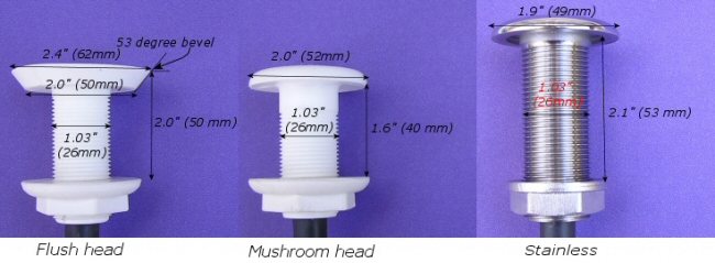
Figure 5-2 Dimensions of through-hulls for Siedarc TM electrodes
5.3.1 Hole preparation
When functioning as intended, each electrode will become hot, especially at the tip, and
experience an impulsive force. So careful hole preparation is crucial. In particular:
- Cored hulls should be hollowed out to a distance of at least 1" and filled with epoxy or other suitable material.
- Newly exposed fiberglass should be surface treated to be made impermeable to water.
- A backing plate is highly recommended.
- Extreme care must be taken to ensure no water seepage.
- If any moisture is found inside hull, the whole hull should be dried.
- Gel coat blisters should be treated by surface planing, and the hull thoroughly dried before electrodes are
mounted.
Any moisture that
is left in the hull is likely to explode during a lightning strike, dislodging the electrode and leaving a hole in the hull.
5.3.2 Flush mounting
1. Using flush-head electrode
Siedarc TM electrodes that are embedded in a flush-head fitting can be mounted so that the outer surface is flush with the hull after making a hole that matches the profile of the fitting. See Figure 5-2(a) for the dimensions. In sandwich hulls, that require an epoxy plug, or new builds, the mold insert shown in Figure 5-2(b) can be used to form the correct hole profile.
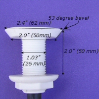 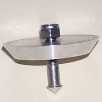
Figure 5-2(a) Dimensions of flush-head fitting (b) Mold insert
2. Using mushroom-head fitting
 An alternative is to use the mushroom-head option. Make a 2.0" diameter hole 0.33" deep in addition to the 1.05" diameter hole through the hull and, if needed, add a fiberglass buildup of at least 3/8" on
the inner hull surface for reinforcement. Then the top of the mushroom head is flush with the hull. Add fairing around the edges. An alternative is to use the mushroom-head option. Make a 2.0" diameter hole 0.33" deep in addition to the 1.05" diameter hole through the hull and, if needed, add a fiberglass buildup of at least 3/8" on
the inner hull surface for reinforcement. Then the top of the mushroom head is flush with the hull. Add fairing around the edges.
Figure 5‑4 Holes needed for
flush mounting using mushroom-head fitting
6 Precautions
Do not use for :
-
Water soaked cores
-
CFC hulls or structures
- in vicinity of a dinghy
-
near a swim
platform
-
anywhere spark could connect with another boat,
dock, or people on shore or in water.
Other precautions are:
-
Electrodes are designed to promote high-current sparks during lightning
strike and should be used accordingly.
- Electrodes are designed to divert lightning current from more sensitive fittings and may be sacrificial.
-
Lightning
is hazardous high-voltage high-current phenomenon and can be lethal, even
from a sideflash carrying a fraction of the current.
- No lightning protection system is 100% effective
and damage can be expected.
- The grounding system is not expected to prevent all sideflashes all of the time.
-
No increased protection is claimed for electronics systems, mast, stays, masthead fittings,
etc.
-
Crew protection is dependent more on bonding between
conducting fittings than the grounding system.
7 Legal notice
This document is the property of Marine Lightning Protection
Inc. It contains information that is
privileged and proprietary and shall not be released in entirety or part to
third parties without the express written consent of Marine Lightning
Protection Inc. Ideas and concepts
presented here may be covered by US Patent Number 6,708,638 and other
US
and international pending patents and may not be used in practice without a
Licensing Agreement.
Technical specifications in this document are based on
information contained in scientific documents, standards published by NFPA,
ABYC and ISO, and original calculations. Interpretations made in this document are limited by the current state
of knowledge of a destructive natural process, lightning, whose behavior is not
completely understood. Marine Lightning
Protection (MLP) disclaims liability for any personal injury, property or other
damages of any nature whatsoever, whether special, indirect, consequential or
compensatory, directly or indirectly resulting from the publication, use of, or
reliance on this document. MLP makes no
guarantee or warranty as to the completeness of any information published
herein. Anyone using this document
should rely on his or her independent judgment or, as appropriate, seek the
advice of a competent professional in determining the exercise of reasonable
care in any given circumstances.
Spark-promoting electrodes are designed to conduct large
magnitude currents and may be subject to localized heating, explosive forces
and hazardous voltages. Reasonable care
should be exercised in their use. No
warranty is given or implied with respect to any use of these electrodes.
Appendix A Case studies
A1
Two case studies
The following two case studies demonstrate the ineffectiveness of a single grounding surface. In both cases:
- the rigging was grounded to the keel ballast;
- the grounding area was well in excess of 1ft2;
-
sideflashes occurred;
-
the sideflashes blew holes in the
hull at the waterline.
A1.1
Current flow through grounded keel
A1.1.1 Observations
The owner of this sailboat made the observations in Figure A1‑1 . The bottom of the mast was connected to a keel bolt.
Figure A1‑1 Lightning damage to grounded boat in fresh water
Interesting features in this case are:
-
The holes in the ballast indicate that current had flowed out of the keel.
- Two sideflashes made holes that formed through the hull fore
and aft.
- The origin of each sideflash was a stay.
- Both sideflashes connected through intermediate
conductors.
This case demonstrates the risk factors associated with:
-
the ends of stays, typically chainplates;
- electrically-
isolated conductors;
-
the waterline.
A1.1.2 Remedy
Possible remedies are:
-
additional grounding electrodes near the waterline in the general vicinity of the
backstay/organizer and forestay/water tank;
-
bonding connection between aft stay and Al
organizer;
-
potential equalization between forestays and water tank.
Note however that equalization by bonding is not possible
for the water tank.
A1.2 Current flow
avoiding grounded ballast
A1.2.1 Observations
The lead ballast in this case was connected to the rigging
via down conductors from the side chainplates. The owner reported similar symptoms of holes
at the waterline.
Figure 7‑2 Lightning damage to grounded boat in fresh water
Of particular note were:
-
There was no indication that current flowed out
of the keel.
- The down conductors initiated sideflashes.
- The holes were at the waterline.
A1.2.2 Remedy
The main remedy here is to add a grounding electrode below
each chainplate near the waterline.
|