The science and technology of yacht lightning protectionHistoryWhen Benjamin Franklin invented the lightning rod in 1750, he noted that it could also be used to protect ships. It was not long before the first ships were to benefit from his ideas. In the late 18th century the sailing warships of the British navy were fitted with lengths of anchor chain to prevent their wooden masts from splintering when struck by lightning. Franklin himself was unsure of the actual mechanism, thinking initially that a pointed rod would discharge the thunderstorm "for if there be a rod sharpened ... the electrical fire would be drawn out of a cloud" but five years later covering all bases by adding "pointed rods would either prevent a stroke or would conduct it so that the building should suffer no damage". For whatever reason, this technology worked. The discharge physics of the lightning strike to ground would not be well understood until research done in South Africa in the 1930's and later.In the intervening centuries scientific opinion has come down squarely on the side of Franklin's last opinion - that a lightning rod protects a building by offering a suitable path for the current to flow. Still, modern day refinements for marine protection somewhat mirror the historical record. Although a code developed by ABYC definitely improves lightning safety, research continues into the underlying science. In a paper published by IEEE (the Institute of Electrical and Electronic Engineers) in 1991, Ewen Thomson of the University of Florida tested this code by applying the traditional science used in lightning protection systems for ground installations. The traditional science, reflected in terms such as "ground resistance" and "step potentials" models voltage gradients as a consequence of current flow in the ground (or water). Thomson concluded that key changes were needed. While some changes were trivial to implement, such as upgrading down conductors from #8 gauge copper to #4 gauge copper, others were highly impractical. In particular, Thomson noted that hull damage to sailboats struck in fresh water was so extensive, even when the boat had a good connection to the keel, that multiple grounding surfaces were needed over an extensive underwater area, a requirement is very difficult to fulfill in practice. Of even more concern were some types of boat lightning damage that were impossible to explain with the traditional scientific model. In the light of these inconsistencies, Dr. Thomson concluded, in a yet unpublished study, that key assumptions in the traditional model were invalid Removing these assumptions and reinterpreting the fundamental science has resulted in a new model that enabled innovative technology to be developed to overcome the above practical limitations. This technology is now covered by a patent issued by the University of Florida and licensed solely to Marine Lightning Protection Inc.ProblemsThe discharge mechanism for lightning strikes to ground is very well understood and explained in detail in many of Professor Martin Uman's books. A detailed explanation of this strike mechanism for a lightning strike to a boat written with the layman in mind is given in the Florida Sea Grant publication SGEB17. From a yacht's point of view, the impending lightning strike begins when a column of charge has been lowered to within a few tens of meters of ground in a process called the stepped leader. At this point currents begin to flow, both up towards the stepped leader, and down into the water. Current flows either from electronic conduction inside conductors or in the form of propagating charged streamers following ionization of air or water. Eventually one of the upward streamers, termed the attachment streamer, connects with the stepped leader to form a physical attachment to the boat. At this stage the thundercloud is effectively shorted to ground by a continuous ionized channel, and the peak current flows with an amplitude of several tens of kA with a rise time of about 100ns during the return stroke phase. This peak current decays in a few tens of microseconds but may be followed by a lower level continuing current (~few hundred amperes) for perhaps several hundred milliseconds. While at a much lower level, the continuing current is the process responsible for the largest heating effects.The challenges of protecting against damage from this high voltage discharge in the case of a boat lightning strike are not trivial :-
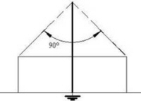
Lightning processesAs far as a boat is concerned, the major processes are:
AttachmentSince there is no scientifically proven method to repel it, the fundamental problem in yacht lightning protection is how to deal with lightning when it strikes. Where the lightning channel attaches to a boat is determined by the geometry of topside conductors on the boat and the location of the downward-going stepped leader relative to the boat. For example, if the stepped leader is heading for the water behind the boat, aft conductors are more likely to be struck. In general, the taller the conductor, the higher the probability that its upward streamer will be the one that connects with the stepped leader, thereby completing the ground channel for the lightning. The conductor in the lightning protection system intended to make this connection is termed the air terminal, or, more commonly, the lightning rod. In this respect, research reported by Dr. Charles Moore and associates in New Mexico only two years ago finally resolved that blunt lightning rods are actually more effective than the traditional sharp pointed rods. The tendency of a tall conductor to attract the lightning strike, by preferentially launching the final connecting streamer, has resulted in the idea of a "cone of protection". This somewhat flawed idea holds that a vertical conductor forms an effective cone of protection, the apex of the 90 degree cone being at the top of the conductor, and protects the circular area of the cone's base. The idea is flawed in that a vertical conductor does not eliminate the electric field on the ground within this "protected" circular area. Any conductors inside the area, people included, may give rise to upward streamers if this electric field reaches breakdown strength. A better arrangement is to have conductors arranged around the area to be protected, or, better yet, forming an umbrella overhead, where the outer edges of the umbrella are connected to down conductors leading towards the water.Hence the major concern regarding the lightning attachment is to ensure that the lightning attaches to, and causes current to flow in, only an air terminal, or other termination conductors, rather than more vulnerable conductors such as crew members, electronics, etc. Charge accumulation & current flowAfter attachment, conductors, and usually all conductors on the boat, conduct current, even those not connected directly to the lightning protection system. This includes wiring and internal circuitry in and between electronic items. In addition, charge accumulates on conductors and can initiate sparks to form new conducting channels as the lightning charge strives to lower its potential energy. Since the absolute voltage of the lightning source is high enough to ionize air over a distance of several miles, sufficient energy is available to form a spark of any length on the boat if needed to bridge an air or fiberglass gap. Simple circuit concepts such as the path of least resistance are of limited use in this electromagnetic maelstrom but the non-linear nature of this high voltage, high current situation means that the electromagnetics are too complicated for complete analysis. Add to this the necessity for some sensitive transducers to be placed near the mast head and others immersed in the water, and it is no wonder why insurance underwriters use the term an "Act of God" when CDI ignition systems are destroyed, knot meters are blown out of the hull, and masthead antennas are vaporized, rendering the boat immobile, sinking, and without means of communication. This is the complicated physical background governing the design of the conductor system to conduct the lightning charge from the air terminals to the grounding conductors.So, the role of the down conductors, those connecting the air terminals to the grounding conductors, is to conduct the lightning current towards ground, preclude all sideflashes, protect transducers, and minimize electromagnetic coupling into electronics. Charge dissipation into the waterFiberglass is such a good insulator that it is used to make insulators for high voltage installations. Nevertheless, the lightning voltage is more than enough to cause electrical breakdown through a fiberglass hull if no alternative path is provided, and frequently even if one is. Each penetration leaves a charred hole and much more extensive internal damage. Grounding conductors (electrodes) are intended to form a bridge into the water to eliminate this hull damage. However, a single ground plate is inadequate to prevent sideflashes, necessitating multiple interconnected conductors. These cause a whole new set of problems:
Carbon deposits after lightning strikes trace out the paths followed by sparks forming from immersed conductors, both those grounded and those that are isolated. A detailed discussion of this effect is given in a letter published in Professional Boatbuilder. Briefly, charge accumulates on all conductors on the boat, even when current is flowing into the water. The charge density is largest close to the water and on sharp corners and edges of conductors, which is thus where sparks are most likely to start. So sharp corners are highly desirable on the outside of grounding plates and are recommended in most standards. As well as initiating current flow, spark formation reduces the grounding resistance, thereby lowering the voltage of the whole protection system. There is experimental evidence that the eventual effective area of the sparks formed from at the water surface above-water fittings may be hundreds or thousands of square feet. See a brief discussion of this mechanism below. In summary, the major problem with charge dissipation into the water is how to provide the appropriate number and distribution of grounding conductors, to eliminate sideflashes, while minimizing the corrosive effects of multiple immersed conductors that are bonded together. Sideflash formationWhile sharp corners are beneficial on grounding conductors, this is definitely not the case for conducting fittings that are not supposed to act as grounding electrodes. Any spark from these is a sideflash, that can injure crew, blast a hole through the hull, and destroy electronics. Uncontrolled sideflashes are to be avoided. On the other hand, the location or shape of fittings frequently cannot be changed. For example, a sideflash from a chainplate to the water is a very common occurrence.
By analyzing case studies such as these we have gained an understanding of the causes of sideflashes, their association with standard fittings, and how they form and propagate. We identify two distinct types of sideflash:
SolutionsOverviewThe only viable solution is an integrated approach. Key elements in the development of this are:
Addressing the central-conductor problemUnfortunately, the general consensus for designing a marine lightning protection system fails on all of the above counts. This is represented in the figure below that is roughly consistent with standards published by ABYC, NFPA (before 2008) and ISO. The main features of this are: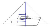
The easiest way to appreciate the fundamental issues with this approach is to design a lightning protection system for a building using the same principles. The building system would look something like this: New method adds lightning conductors around perimeterObviously, buildings are not protected this way. Rather, the typical building system has multiple air terminals around the roof edges, down conductors on the outside, and ground rods around the perimeter. Also, the air terminal heights and
locations are typically determined using a rolling sphere model rather than
an inverted cone. Placement of air terminals, down conductors, and ground rods on the outside guides the
lightning current outside the structure, minimizing both step potentials and
electromagnetic interference (emi). Translating these concepts to a marine
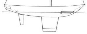
system results in the design illustrated to the right, where the lightning
conductors are shown in blue. The dashed lines show the zones of protection based on the inverted cone and rolling sphere methods. Since the bow rail can be considered to be an air terminal, then the rolling sphere method
gives a protective zone that covers the whole interior of the boat. heights and
locations are typically determined using a rolling sphere model rather than
an inverted cone. Placement of air terminals, down conductors, and ground rods on the outside guides the
lightning current outside the structure, minimizing both step potentials and
electromagnetic interference (emi). Translating these concepts to a marine
system results in the design illustrated to the right, where the lightning
conductors are shown in blue. The dashed lines show the zones of protection based on the inverted cone and rolling sphere methods. Since the bow rail can be considered to be an air terminal, then the rolling sphere method
gives a protective zone that covers the whole interior of the boat.
We call this arrangement of conductors on the outside of the boat the ExoTerminalTM system. The new aspects of this design are:
Discharge mechanism for the SiedarcTM electrodeThe key component in this new system is our patented SiedarcTM electrode. This was invented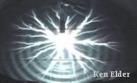 in 2001 (US patent
#6,708,638) on the empirical justification that lightning conductors should
be placed at the locations where lightning damage is frequently seen, that
is, just above the waterline. Since
then, our experiments to investigate the sparking mechanism have revealed
that current flow in the form of spark channels propagates in the air just
above the water surface and that the extent of these channels are much
longer than might be expected. For
example, the photo on the right shows a sparking pattern about 15" in
diameter from a spark that was generated at the tip of a SiedarcTM electrode connected to a 10kV
source. Ordinarily, 10kV is capable
of forming a spark of only a fraction of an inch in air. This type of phenomenon has also been observed during
much longer sparks to water and actual lightning to ground. Prof. Moore and colleagues at
New Mexico Tech. explain the
origin in terms of charge that is induced on the surface of the water or ground in
response to the charge on the lightning channel. An observation by one of our customers,
who had both SiedarcTM electrodes just
above the waterline and immersed HStrips installed on his boat, illustrates the proactive role that SiedarcTM electrodes are likely to take
during a lightning strike. While
sitting in the cockpit during a thunderstorm when several strikes hit
within several hundred feet of his boat, he observed what he describes as a
"shimmering shivering orange glow" in the shape of a spider web
that stretched for the length of his boat and more than 100' out from his
boat on the surface of the water. This occurred several times, and lasted 1-2 seconds each time. Note
that these were not lightning strikes. A reasonable interpretation of this
phenomenon is that, during each event, a glow discharge in the air just
above the water originated from one or more electrodes in response to
charging of the boat from corona discharge (that is, St. Elmo's fire) off
the mast top. in 2001 (US patent
#6,708,638) on the empirical justification that lightning conductors should
be placed at the locations where lightning damage is frequently seen, that
is, just above the waterline. Since
then, our experiments to investigate the sparking mechanism have revealed
that current flow in the form of spark channels propagates in the air just
above the water surface and that the extent of these channels are much
longer than might be expected. For
example, the photo on the right shows a sparking pattern about 15" in
diameter from a spark that was generated at the tip of a SiedarcTM electrode connected to a 10kV
source. Ordinarily, 10kV is capable
of forming a spark of only a fraction of an inch in air. This type of phenomenon has also been observed during
much longer sparks to water and actual lightning to ground. Prof. Moore and colleagues at
New Mexico Tech. explain the
origin in terms of charge that is induced on the surface of the water or ground in
response to the charge on the lightning channel. An observation by one of our customers,
who had both SiedarcTM electrodes just
above the waterline and immersed HStrips installed on his boat, illustrates the proactive role that SiedarcTM electrodes are likely to take
during a lightning strike. While
sitting in the cockpit during a thunderstorm when several strikes hit
within several hundred feet of his boat, he observed what he describes as a
"shimmering shivering orange glow" in the shape of a spider web
that stretched for the length of his boat and more than 100' out from his
boat on the surface of the water. This occurred several times, and lasted 1-2 seconds each time. Note
that these were not lightning strikes. A reasonable interpretation of this
phenomenon is that, during each event, a glow discharge in the air just
above the water originated from one or more electrodes in response to
charging of the boat from corona discharge (that is, St. Elmo's fire) off
the mast top. 
In the light of these observations, we propose the mechanism illustrated in the animation on the right to explain how SiedarcTM electrodes conduct the negative lightning charge to the positive charge induced on the surface of the water. The sequence of events is as follows:
Boat typesWhile the above concepts can be adapted to any type of boat, each one has its own particular set of problems. General approaches for different classes of boats are as follows:
See our gallery of systems for examples. JetskisSmall open boatsThe vast majority of lightning deaths on boats occur on small open boats. In other cases boaters have been knocked unconscious but eventually recovered, as do the majority of strike victims. Hence administering CPR to an unconscious crew member is the top priority. An excellent source of information for lightning survivors is Michael Utley's website. Hence in the case of an open boat, a good lightning protection system may indeed save a life. The principles are the same as for any boat – air terminals to provide a strike point, external conductors to form a protective cage around the boat, and multiple grounding terminals to disperse the current away from the boat. Overhead conducting fittings such as T-tops and biminis can be life savers when they are integrated into a complete system. Otherwise they are potential sideflash hazards. We have developed products and techniques that can be used on small boats to dramatically lower these risks. Our collapsible air terminals are designed to bolt directly onto a handrail, bimini top, or the deck, thereby attracting the strike point precious feet away from the crew. SiedarcTM electrodes, installed above the waterline, provide a low-drag option for grounding. And our through-hull connecting studs and know how enable existing metallic fittings such as bow rails, T-tops, and biminis to be interconnected to form a protective conducting shield. However, given the extreme nature of the hazard and limited space available, practical solutions still involve a high degree of danger and no one can give any guarantees. Discretion definitely should prevail.Close to shore, an understanding of the partial protection that can be afforded by nearby tall objects such as trees is useful. That is, a nearby tree tends to attract lightning away from the ground around it. Note the words "tends to" rather than "will". However, the common sense rules of land also apply here. In particular, do not get too close to the tree (within about 20 feet of the trunk or directly below overhanging branches) since a sideflash may form from the tree if struck. The cardinal rule is to avoid being on an open boat during a thunderstorm, even if the fish are biting! Get out of the boat and into a metallic vehicle or large building, but avoid any unprotected small shelter, especially one with a metal roof and no lightning protection. Air boatsAn air boat has the same risk factors as small open boats – a direct strike to the boat occupants being the major danger. In fact, since the operator is typically on a raised seat the risk may be even higher than for an open boat. Fortunately the solution for a metal-hulled air boat is very straightforward. This involves adding conductors (air terminals) that can be attached directly to the deck or motor housing to provide alternative attachment points for the lightning strike. See our airboat page for more details. For an airboat with a fiberglass hull, a grounding system similar to that in a small open boat is also needed.Trailerable sailboatsIn contrast to a small open boat, the metallic mast and rigging of a sailboat forms an effective in-built protection against direct attachment to crew members. Also, the typical aluminum mast usually has sufficient cross section to act as a reasonable down conductor (but, in a small boat, the stainless steel rigging does not). The mast is, however, also a hazard since a sideflash from the mast base is possible. In one case, sideflashes occurred from the mast base through the hull in a cat-rigged sailboat (in salt water) whose mast base was well bonded to a keel bolt. Add to this the typical location of the mast base above the living quarters and the risk to crew becomes obvious. In order to conduct the lightning current from the mast to the water without involving the crew, the best solution is to route all lightning conductors around crewed areas and provide multiple grounding paths as explained above. The type of ballast also is an important factor. A metallic swing keel effectively brings the water potential inside and becomes a hazard if it is not bonded to the mast. That is, a sideflash could spark from the mast base through a crew member to the keel if these potentials (mast and keel) are not equalized by bonding. A water ballast presents a whole new set of problems. Since the water in the ballast is a conductor, it presents a similar sideflash hazard to a metallic keel but bonding is impossible. Also, if the sideflash does connect to the ballast water, exiting sideflashes from the ballast to the water outside are likely to blow holes through the hull. In this case external lightning conductors become crucial. The availability of HStripTM immersed grounding strips and SiedarcTM electrodes to terminate these external conductors provides for a practical and reasonably priced solution to this particular problem.Powerboats with metal superstructureThe principles for effective lightning protection on smaller boats are the same as those for larger boats. That is, form an ExoTerminalTM system. Grounding terminals and interconnections around the perimeter shield the region inside, while attachment conductors (air terminals), also around the perimeter, attract the strike point away from the boat's interior. Superstructure such as a metal-framed bimini, metal outriggers, and metal cabin framing act in a similar fashion to the metal rigging of a sailboat. They can be incorporated into a lightning protection system to act as air terminals and form part of the conducting cage. Some, but not a lot, of modifications are in order. Consider the typical fisherman. While there is usually a lot of deck-top metal, not all of it is above head height, which is an obvious problem. For example, a wraparound bow rail is in the optimum place to be used as part of the system but knee-high is nowhere near high enough to attract the strike that precious few feet away from a deck hand. We are presently developing a solution to this – a lightning rod that attaches to the bow rail but that can easily be laid flat for docking, etc. While this does not guarantee the safety of the deckhand, it considerably skews the odds in his or her favor. Other techniques such as overhead catenary wires can skew the odds even more. In the absence of connections to a good grounding system, however, this same metal superstructure becomes instead an electrical hazard since it acts as a launching pad for uncontrolled sparks. Also, to minimize the shock risk to the helmsman, the engine and steering controls should be bonded to the lightning protection system to ensure that everyone floats at the same potential. The grounding system on any boat should comprise multiple grounding terminals that include at least one square foot of immersed area. For the immersed area, outboard and stern drives can be used, or additional grounding strips can be added. SiedarcTM electrodes complete the grounding network. How many electrodes and where they are best placed depends on the individual boat. However, some locations are no-brainers, such as directly below each outrigger on a fisherman. Owing to the proximity of the lightning attachment point to occupants, even the best possible lightning protection system still presents an extreme risk on a small boat so that there can be no guarantees. A lightning protection system hence should be regarded as a good insurance policy that could just save your life.Cruising sailboatsAny liveaboard yacht requires a high standard of protection to ensure crew safety and hull integrity. Further, any yacht that ventures into blue water needs to be self sustaining after a strike. Larger sailboats have the advantage that a large interior volume means that the lightning protection system can be routed away from living quarters. However, complex control systems, dispersed electronics sensors, and carbon fiber or metal reinforcing means many conductors, each being a potential source for a sideflash. While immersed conductors such as propellers, bronze seacocks, and metal ballast have the potential to be incorporated into the grounding system, doing so raises the risk of corrosion and their grounding effectiveness is compromised if the surfaces are painted or covered with fiberglass. Also, dezincification of bronze through-hulls leaves them porous and weak and unsuitable for lightning grounding. Judicious placement of grounding electrodes is vital to ensure that the only lightning exit points are those that are planned.Passagemakers & blue water power yachtsAn ocean-going power yacht has more risk factors than any other type of boat. Large open deck spaces with an absence of natural lightning rods raise the risk of a direct attachment to anyone on deck. Any on-deck spa or pool further increases the odds of electrocution since a wet human body is more likely to conduct a lethal current than a dry one. Without adequate air terminals, at least upward-going streamers, and possibly direct lightning attachment, is likely for elevated transducers such as antennas, radar, and weather sensors. The natural path to ground in this case is then via on-board wiring through the main instrumentation cluster, likely destroying most other electronic systems as well. This may include electronic control systems for steering and engines that are much more susceptible to lightning damage than manual ones. Hence mechanical redundancy is crucial. In-built conductors such as water in tanks, carbon fiber reinforcing, metallic fittings, and power plants are all potential sources for sideflashes, perhaps through crew, passengers or the hull. As with cruising sailboats, there are many immersed conductors that may be incorporated into the grounding network but doing so raises the risk of corrosion and their grounding effectiveness is compromised if the surfaces are painted or covered with fiberglass. Our proprietary grounding technology is designed to fix this problem. Passagemakers do also have some advantages. Extensive weather sensing capabilities can be supplemented with thunderstorm and lightning sensors to warn the crew of electrical hazards. Also, extensive metallic superstructure and handrails on the periphery of the vessel are already in the ideal location to form part of the external conducting shield that we call the ExoTerminalTM grounding system. Just add air terminals, six SiedarcTM electrodes, one square foot of immersed ground strips, surge suppressors for antennas, and interconnections, and a superior lightning protection system is the result. Sample installations are available for a Mirage Great Harbour Pilothouse and a Nordhavn 55.HovercraftThe principles for protecting a hovercraft against lightning are exactly the same as those applied to boats with one exception: since the hovercraft is not in contact with the water, the concept of an immersed ground is meaningless. This should make no difference to the layout of lightning conductors, which still need to envelop the craft. Since the skirt is nonconducting, we can place the grounding terminals - in this case they will all be SiedarcTM electrodes - at the lowest points on the rigid body.Instrumented buoysAn instrumented buoy is very similar to a yacht in that it is a floating isolated platform with sensitive electronics, usually including submerged transducers and raised components such as solar cells and/or telemetry antennas. Even if the buoy itself is metal, these submerged and raised components are very sensitive to damage even from close lightning strikes. The consequence of a disabled buoy might range from loss of valuable data while the equipment is being replaced in a scientific sensor, to a shipping hazard in the case of a navigation buoy. |
||||||||
Contact
Please call or email if you have any questions.
|
||||||||
 This figure shows what happened in one case. Even though
current definitely flowed out of the grounded cast-iron keel, as evident
from "thousands" of holes in the keel,
This figure shows what happened in one case. Even though
current definitely flowed out of the grounded cast-iron keel, as evident
from "thousands" of holes in the keel,