|
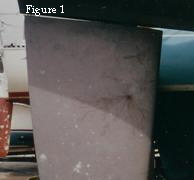
Published in Professional BoatBuilder Number 88 April/May 2004 pp.4-6  Lightning Protection To the Editor: Nigel Calder’s article on Lightning Protection (PBB, December 2003 pp. 26-43) gives an excellent presentation of the state of this problematic area. His final comments, “no practical measures can be guaranteed to protect sensitive electronic equipment”, are especially important in light of recent innovations to engine design using electronic devices. For example, mechanical diesel engines are much more immune to lightning damage than gasoline engines with CDI ignition. However, according to Sven Donaldson’s article “Turning a Page in Diesel Technology” in the same issue, “the days of the all-mechanical marine diesel are likely numbered” and the new designs will be loaded with electronics. This raises the risk of catastrophic engine failure in mid ocean after even a close lightning strike. While the Lighting Protection article correctly stresses the need for grounding, the author’s treatment of the technicalities of ground plate design and function merit further discussion. Consider the statement “Research suggests that a lightning strike is dissipated primarily from the edges of a ground plate, so a long metal strip (say, 1” by 12’) may be up to six times as effective in dissipating a strike as a square metal plate with the same surface area.” This appears to be derived from ABYC Standard E4, section E-4.9.1.2 NOTE 2 “A strip approximately 1” wide and 12’ long has nearly six times the amount of edge area exposed to the water, which, compared to the ground plates, will improve the dissipation of charges.” The ABYC standard, in turn, may be an interpretation of my 1991 article (“A Critical Assessment of the US Code for Lightning Protection”,IEEE TRANS. EMC, Vol. 33, pp.132-138, 1991) where the advantages of a long narrow ground strip over a square ground plate are discussed. Specifically, the resistance of a 10m x 9mm strip (that is, a one square foot area in a 30’ strip) is estimated as 27 ohms compared with 72 ohms for a square plate of the same area. Hence, for fresh water “The maximum voltage (for the long (10m) strip) for a 30kA current is 810kV, which is … one third that for a single ground plate with dynamic grounding. Although this is still high enough to initiate sideflashes to the water, by placing a conductor along the centerline, we establish an equipotential that inhibits sideflash formation from any conductors directly above the centerline. This includes both the forestay and backstay, which are conductors that are highly susceptible to initiating sideflashes if only a single ground plate is used.” The term “dynamic grounding” refers to the well-established phenomenon whereby sparks form from grounding electrodes (such as ground plates) to increase the effective surface of the electrode. So the resulting “dynamic resistance” is lower than the conventional resistance. Although not quoted in the IEEE article, a 12’ strip has a dynamic resistance of about 35 ohms, one half the dynamic resistance of the square plate (not one sixth). This modest improvement in grounding resistance results in a halving of the voltage of the lightning protection system but this is still high enough to cause sideflashes. Of more importance, and missing in the later interpretations, is that the long strip should extend over the length of the boat to deter sideflashes from any conducting fittings directly above the strip, especially the forestay and the backstay. The same idea can be extended to sidestays, but who is going to place a ground strip from chainplate to chainplate with edges nicely exposed to maximize drag? The existence of underwater sparks is evident from arcing patterns either etched in bottom paint or imprinted as carbon traces on hulls after lightning strikes. The length of these varies from a couple of inches to a couple of feet, depending on their spacing. Sparks are more likely to form from edges and corners, but have also been observed from the flat surfaces of metal keels and encapsulated conductors such as rudder posts and fiberglass-encased lead ballast. All photographs below were taken by Greg Davis of Davis and Company Ltd. This boat had copper bottom paint and was struck in a freshwater lake. Figure 1 shows both carbon arcing and etching in copper bottom paint near an encapsulated rudder post. There were only two exit points on this side of the rudder and the sparking extent of the larger pattern was about 2’ across.
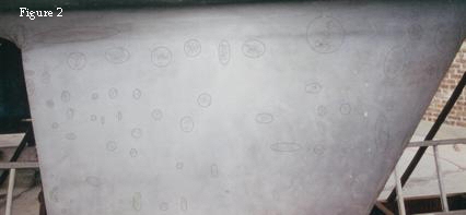
However, there was also evidence that many other sparks formed from keel ballast, bonded through-hulls, propeller shaft, and a transducer. The arcing patterns on the lead keel were much smaller in size, typically a few inches, and more closely spaced (Figure 2). The outer limit of each arc pattern has been marked with an ellipse.
The photographs indicate that spark formation is an integral process during lightning grounding, that is, when currents flow from the grounding conductors into the water. Some insight can be gained into the mechanisms involved by applying some basic physics to the grounding portion of a lightning protection system. The general problem in grounding is to dissipate the lightning charge, which builds up on all conductors in the system as soon as current starts flowing from the lightning rod (air terminal) at the top of the system. The charge to supply this current either flows from the water or is provided by charge of opposite polarity that distributes itself on all surfaces of all conductors in the protection system. In fact, even when current is flowing from the water, for example through a ground plate, charge still accumulates on the system conductors. Charges also separate on ungrounded conductors. The largest charge densities form close to the water and on portions of any conductor where the radius of curvature is small. What determines whether a spark will form is the electric field strength, which turns out to be proportional to the surface charge density. Specifically, a spark forms, and continues to propagate, if the electric field strength at its tip exceeds the critical value needed for electrical breakdown. For conductors that are in contact with the water, such as ground plates, this means that the largest surface charge densities appear on the corners and edges, which are thus where spark initiation is most likely. Once initiated, the spark system tends to branch extensively, with each branch propagating in a general radial direction so that a hemispherical conducting (or equipotential) region is formed that is centered on the initiation point. That is, highly branched sparks effectively fill the region with a highly-conducting plasma. As this region spreads, the effective area of the grounding surface - the outer surface of the equipotential hemisphere - increases so that the charge density and electric field at the surface both decrease, eventually dropping below the critical value. At this point the sparks stop forming, leaving behind a hemispherical equipotential volume with radius r0. Any part of the conductor inside r0 is at about the same potential as the initiation point so that no electric field, and thus spark initiation, is possible. In the event that two points initiate sparks simultaneously, the two equipotential regions will combine but the overall size of the equipotential region will not differ much from the hemisphere of a single initiation point if the points are much closer than r0. In this respect, for a two-edged thin conducting strip the second edge does not add much, and possibly nothing, to the equipotential region arising from the spark system of the first. So, although a long thin conductor gives a lower dynamic ground than a square plate, we cannot conclude that the more edges the better since any edge inside the region of sparking from another edge or point (an equipotential region) is unlikely to produce additional sparks. Ewen Thomson, Ph.D. Marine Lightning Protection Inc., Gainesville, Florida
|
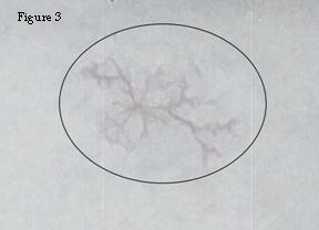 The patterns display the dentritic structure typical of the branching nature of sparks (see the magnified Figure 3) and indicate how important sparks were during the grounding process in this strike.