Grounding concepts for a marine lightning protection system1. ScopeThe scope of this document is to introduce the major concepts governing sideflash formation and mitigation in the design of a marine grounding system. Physical principles involving potential, electric field, potential equalization, and sideflash formation are discussed. These principles are then applied to the general layout of grounding electrodes, main conductors, and bonding conductors in a marine grounding system. Two case studies show damage patterns that are consistent with the concepts presented.Details concerning the use of grounding electrodes in an actual system is given at our Grounding Guide page. 2. Terminology2.1. Grounding the process whereby current flows from a water terminal towards or into the water.When a conductor is placed in the water to act as an exit terminal for the lightning current, it is common practice is to refer to it as a "ground plate". However, this is a misnomer as the voltage of any water terminal is actually that of the whole lightning protection system, which is significantly different from zero volts. Instead, the term "grounding" is preferable to indicate the flow of current into the ground medium (water), rather than a point on an equipotential at ground potential. One corollary to this is that a conductor does not need to be immersed in the water to deliver current into the water. In fact, a conductor in the lightning protection system can act as a water terminal if sparks form from it, and there are cases when a down conductor, a mast base and even a sink drain have inadvertently acted to ground the lightning to water. 2.2. Grounding electrode a conductor connected to the lightning protection system intended to conduct current to the water or water surfaceConsistent with terminolgy now used by the National Fire Protection Association in NFPA780, we use the term "electrode" to reflect its particular function as a terminal through which current flows. We distinguish between two types of grounding electrodes:
2.3. Sideflash any discharge occurring during a lightning strike that involves the formation of a spark channel from any source other than an air terminal or a grounding electrodeSideflashes typically involve conductors on the boat, that may include water tanks and crew members. We distinguish between two types of sideflashes:
2.4. Main conductor - conductor used in the lightning protection system wherever current flow is expected to be generally towards the water2.6. Bonding conductor conductor used in the lightning protection system for potential equalization only3. Lightning mechanismFrom a yacht's point of view, the lightning strike begins when current flows from any part of the lightning protection system.This is typically tens of milliseconds after the lightning has started in the cloud. Specifically, after a column of charge has been lowered to within a few tens of meters of ground, in a process called the stepped leader, current flows off the top of the lightning protection system up towards the stepped leader in a process termed the attachment streamer. This current either charges the lightning protection system or is accompanied by a current flow into the water, or both. Current flows either from electronic conduction inside conductors or in the form of propagating charged streamers following ionization of air or water and probably totals some hundreds of amperes. Eventually the attachment streamer connects with the stepped leader to form a physical attachment to the boat. At this stage the thundercloud is effectively shorted to ground by a continuous ionized channel, and the peak current follows, with an amplitude of several tens of kilamperes with a rise time of about 100ns during the return stroke phase. This peak current decays in a few tens of microseconds but may be followed by a lower level continuing current (~few hundred amperes) for perhaps several hundred milliseconds. While at a much lower level, the continuing current is the process responsible for the largest heating effects. For a more detailed discussion of all of the processes in a lightning strike, refer to our Science & Technology page.4. Physical concepts4.1. Potential4.1.1. DefinitionPotential is the energy per unit charge.The lightning protection system becomes charged, usually through the air terminal, by either a direct flow of charge from the lightning channel or by an induced flow of charge into the surrounding air when there is no direct connection to the channel.In either event it becomes energized.As the lightning protection system discharges, this energy is converted into various forms such as heat, electromagnetic, light, and sound, usually in high-power bursts that can do considerable damage, both mechanical and electrical.At any instant the total charge on the lightning protection system is the difference between the charge that has flowed into the air, usually off the air terminal, and that which has been conducted into the water .Whenever there is excess charge on the lightning protection system, the system is energized, and its potential is raised above ground (see Section 4.1.2 ).4.1.2. GroundPotential is the same as voltage, both being represented by "V". Unlike a two-dimensional electric circuit where the voltage can be defined relative to some well-defined "ground" wire or plane, a boat consists of a complicated three-dimensional system of conductors, some of which are connected, that is sitting on another conductor, the water, and nothing can be regarded as being at "ground" potential.In this respect, a boat being struck by lightning should be regarded in the same manner as a system with a positive ground, corresponding to the lightning protection system, where the negative terminal is far from the boat. The fact that ground potential cannot be reached is actually not a problem since the major concern in practice is the potential gradient, or rate of change of potential with distance.4.1.3. EquipotentialsIf the potential of the lightning protection system is V0, and we assume that the potential is zero far from the boat, then at a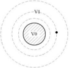 particular point in between the potential has an intermediate value .A region or surface where the potential has
the same value is termed an equipotential. This is the case inside and on the
surface of a conductor. Close to a
conductor, the equipotentials are surfaces that have a similar shape to the
surface of the conductor.For example, the lightning protection system
and all conductors connected to it approximate an equipotential region at
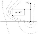
potential V0.If the
lightning protection system consists of one long cylindrical down conductor,
then the equipotential surfaces are also cylindrical as shown in Figure 4‑1
.The potential at any point on an equipotential
surface is at the potential of that surface.For example, the point shown in Figure
4‑1 is at the potential V1, where V0 > V1 > 0. particular point in between the potential has an intermediate value .A region or surface where the potential has
the same value is termed an equipotential. This is the case inside and on the
surface of a conductor. Close to a
conductor, the equipotentials are surfaces that have a similar shape to the
surface of the conductor.For example, the lightning protection system
and all conductors connected to it approximate an equipotential region at
potential V0.If the
lightning protection system consists of one long cylindrical down conductor,
then the equipotential surfaces are also cylindrical as shown in Figure 4‑1
.The potential at any point on an equipotential
surface is at the potential of that surface.For example, the point shown in Figure
4‑1 is at the potential V1, where V0 > V1 > 0.
4 ‑ 1 Equipotential surfaces around cylindrical conductor 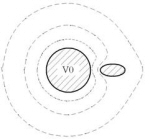 If a very thin conductor with no excess charge is now
inserted parallel to the down conductor at the point shown in Figure 4‑1
, it does not change the situation so that its
potential is equal to that of the equipotential surface that it lies on, V1,
and the shapes of the equipotential surfaces are the same as before. However, if the uncharged conductor is not
very thin, the shapes of all of the equipotential surfaces are changed to
satisfy the condition that the conductor surface is also an equipotential, as
shown in Figure 4‑2
.This distorts
the shapes of all the equipotential surfaces.hile the actual potential of the conductor may still be close to V1,
the equipotentials between the conductor and the cylindrical conductor are
compressed so that the potential gradient is increased in this region. If a very thin conductor with no excess charge is now
inserted parallel to the down conductor at the point shown in Figure 4‑1
, it does not change the situation so that its
potential is equal to that of the equipotential surface that it lies on, V1,
and the shapes of the equipotential surfaces are the same as before. However, if the uncharged conductor is not
very thin, the shapes of all of the equipotential surfaces are changed to
satisfy the condition that the conductor surface is also an equipotential, as
shown in Figure 4‑2
.This distorts
the shapes of all the equipotential surfaces.hile the actual potential of the conductor may still be close to V1,
the equipotentials between the conductor and the cylindrical conductor are
compressed so that the potential gradient is increased in this region.
4-2 Equipotential surfaces around cylindrical conductor in vicinity of isolated conductor 4.2. Electric field4.2.1. Relation to potentialThe equipotential lines on a two-dimensional plot such as in the above figures are analogous to contours on a topographical map. Where contours are more closely spaced, the gradient of the land is steeper.Also, an object falling down a slope moves across the contours at right angles.The electric field represents the gradient of the equipotentials and also crosses each equipotential at a perpendicular.In fact, the electric field is defined as the negative of the potential gradient.ince in three dimensions the equipotentials are surfaces, the electric field is parallel to the normal, where a normal is a vector that is perpendicular to all lines drawn in the surface.In an equipotential region, that is, a volume where the potential is constant, there is no gradient and therefore no electric field.For a perfect conductor the surface is an equipotential so that any electric field is parallel to the normal. Also, the interior volume of a perfect conductor is an equipotential region so that there is no electric field inside. Metallic fittings can be regarded as perfect conductors for virtually all lightning processes.4.2.2. Electric field in waterWhen current flows from the lightning protection system into the water through a grounding electrode, a current density field is established in the water.The shape of this depends on the geometry of the electrode, the hull/water boundary, and the injected current from other electrodes.In contrast to metallic fittings, a significant electric field accompanies this current flow so that the surface of the water is not necessarily an equipotential surface. A reasonable approximation for this relationship is J=σE where J is the current density (in A/m2), σ is the conductivity (in mho/m), and E the electric field (in V/m). The magnitude of the current density depends only on the current provided by the lightning, not the ground impedance.ince fresh water has about 1/100 the conductivity of salt water, electric fields, and hence voltages, are much larger in fresh water.This electric field (or voltage gradient) is fundamental to the problem of sideflash initiation which is thus much more of a problem in freshwater than salt.4.2.3. Breakdown electric fieldAt a high enough value of the electric field (about 107 V/m), the forces on individual air (or water) molecules become high enough to separate out electrons that are then free to move in the general direction of the electric field.That is, the air becomes a conductor and a spark is formed, usually from the surface of a conductor in a perpendicular direction.here the spark is most likely to start can hence be deduced from a plot of the equipotential surfaces by noting where the equipotentials are most closely spaced. While a complete quantitative analysis is best, much insight can be obtained from simple sketches.For example, in the situation shown in Figure 4‑1 and Figure 4‑2 the introduction of the finite conductor results in a larger electric field at its inner and outer extremities.If either, or both, of these exceed the breakdown field, sideflash initiation is likely.
4.3. Potential equalization4.3.1. Bonding
4.3.2. ShieldingAnother technique for equalizing potentials is shielding.This is based on the principle that no electric field exists inside a volume surrounded by a closed equipotential surface as long as each conductor inside the volume is uncharged.ince electric field represents a changing potential with distance, a zero electric field implies a constant potential, that is, the whole volume is an equipotential region. The most common method to ensure that an equipotential surrounds a region is to use a conductor surface to provide the equipotential surface and region, that is, to construct a Faraday cage.The conductor to be protected should be inside the shielding conductor, with the lightning down conductor outside. The down conductor may be either bonded or not, depending on the relative sideflash hazards discussed above.This technique works well for small portable instruments .However, the increased sideflash risk from the lower corners of the Faraday cage means that this technique cannot be used near the water.4.3.3. Grounding
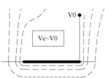
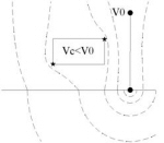
While it is straightforward to simulate the top three sides of a Faraday cage with down conductors, the bottom of the cage needs to be in the water to avoid sideflashes as noted above. In fact, if a long grounding electrode is immersed in the water directly below the conductor the risk of a sideflash from the bottom of the conductor is effectively eliminated, as shown in Figure 4-5 representing a strip-shaped immersed electrode. Since the vast majority of sideflashes propagate towards the water, the shapes of grounding electrodes are more important than the down conductors above the conductor.
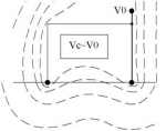
However, it is impractical to construct a network of grounding strip electrodes, which is what is needed to give effective shielding in three dimensions. An alternative technique is to surround the conductor at risk with point electrodes that inject current into the water in such a pattern as to reduce voltage gradients in the vicinity of the conductor's corners. That is, the electrodes reduce the potential difference between the corners of the conductor and the water nearby, as shown in Figure 4-6. Note that in both Figures 4-5 and 4-6 the potential of the conductor is close to that of the lightning protection system even though the two are not bonded. Thus the risk of a sideflash between the down conductor and the conductor is virtually eliminated. 5. Theory for sideflash initiation5.1. Charge removed by lightningThe lightning current is not like a typical current in a circuit since there is no return current. The closest circuit analogy is the discharge of an isolated capacitor by means of a spark between the plates. The return current is actually a displacement current arising from the removal of electric field lines as the lightning current flows to the water. Since the electric field lines that are removed originally terminated on the surface of the water, this means that the charge neutralized by the lightning charge is that residing on the surface. When the lightning current flows there may be transient current flows in the water but any charge injected into the water rapidly migrates to the surface (as determined by the relaxation time τ~10ns in saltwater, ~1 µs in freshwater). Thus any current that is injected into the water through a submersed ground plate ultimately needs to reach the surface. In terms of the current density field, the j field lines initially flow in a perpendicular direction from the surface of the ground plate, but eventually curve towards the surface, and ultimately terminate in surface charge. The next section discusses how sideflashes above the water surface can make a more direct connection to the surface charge.5.2. Sideflash mechanismSee our Science & Technology page for observations of sideflash phenomena, interpretation, and an animation illustrating the mechanism. Since the charge removed by lightning is on the surface of the water, any spark that forms from an above-water fitting, either intentionally from a SiedarcTM electrode or by accident from a metallic fitting, can easily traverse the gap to the surface charge. What follows is then a dynamic process in which the tip of a surface discharge induces and concentrates the charge on the surface of the water just in front of it and hence can propagate for as long as the lightning current is flowing. Once the spark network has been established in the air just above the water surface, it makes an electrical connection to the surface of the water. It is likely that the area of this spark network is orders of magnitude larger than the one square foot specified in most standards, resulting in a far more effective grounding grid. In the next section we describe the factors that determine the relative likelihood for a particular fitting to initiate a sideflash.5.3. Quasi-static field model
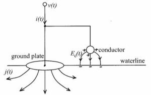
If we assume that the dimensions are much smaller than a wavelength, then both the current density and electric fields are quasi-static and electrostatic concepts can be applied. In this case the electric field at a particular point is proportional to the voltage, and, in particular, Emax(t)={Emax/V}v(t)
where the constant of proportionality {Emax/V}is a geometrical factor, that is, depends only on the shape and location of the fitting. Electrical breakdown occurs if Emax(t) exceeds the critical field strength, about 107 V/m in air. It is useful to express this factor in terms of an equivalent distance, deff={Emax/V}-1 In the case where time variations are slower than the relaxation times, the situation is ohmic so that the voltage v(t) is proportional to the current i(t). This corresponds to the usual interpretation for lightning grounding. Terms such as "ground resistance" and "step potential" imply this linear and in-phase relationship between voltage and current. Since the relaxation times in water are smaller than the characteristic time scales of most lightning processes, the exception being the rise time of subsequent strokes, it is a reasonable assumption when currents are flowing into the water. In this case ground resistance can be calculated for various geometries of grounding electrode. That is, v(t)=Rgi(t) where Rg is the ground resistance. See Thomson (1991). Note however that these calculations do not assume that the current flow terminates on the water surface and hence underestimate the resistance. Also, since propagation phenomena in the water are ignored as well, voltage predictions are probably severely underestimated. In fact, since the wavelengths of electromagnetic waves in water are so much shorter than in air it is even questionable that we can assume a quasi-static model. While it is difficult to estimate the absolute magnitude of the voltages and electric fields involved, the parameter deff is very useful for predicting the relative likelihood of a fitting, or electrode, to initiate a sideflash relative to another. deff can be generally interpreted as the minimum radius of curvature for a perpendicular fitting that is not close to the waterline. Fittings that are further from the lightning grounding electrode, closer to the water, and with smaller radii of curvature are the ones most likely to break down first. In the case of a boat in fresh water, even a lightning protection system with the more effective ground strip is likely to initiate sideflashes from almost any fitting that is not shielded by the strip. The two cases described in the next section illustrate these principles. 6. Two case studies6.1. Common featuresThe following two case studies demonstrate the ineffectiveness of a single grounding surface and reflect some of the principles described above. In both cases:
6.1.1. Current flow through grounded keelIn this case the bottom of the mast was grounded to a keel bolt. Following a lightning strike, the owner commented that thousands of hole had formed at the surface of the keel ballast. He also observed evidence of arcing at both bow and stern..At the bow, he concluded that a discharge had formed between the forestay chainplate and a water tank, and then from the water tank to the water at the waterline, leaving a large puncture hole, as shown in Figure 6‑1 .At the stern, the discharge apparently formed from the backstay chainplate, through an aluminum organizer and rope, and then to the water, once again at the waterline leaving a large hole.
Figure 6‑1 Lightning damage to grounded boat in fresh water There are several interesting features in this case.
In order to provide for adequate protection in this case the following remedies would be useful:
6.1.2. Current flow avoiding grounded ballastAs in the above case, the lead ballast here also was connected to the rigging, but this time via down conductors from the side chainplates.hile the owner reported similar symptoms of holes at the waterline, there were none at the surface of the ballast. Further, the holes were close to the down conductors connecting the sidestay chainplates to the keel bolt.
Figure 6‑2 Lightning damage to grounded boat in fresh water Of particular note here were:
7. Implementation in a lightning protection system7.1. ObjectivesThe primary objective for a lightning protection system should be to minimize electric fields inside the boat so that both sideflash risk and the hazard of high potential differences are reduced.Some specific techniques that address this main objective are:
7.2. Sideflash hazardsCalculations, some of which have been presented in Section 5,
predict that sideflashes are inevitable in fresh
water, are initiated preferentially from conducting fittings with small deff , and occur almost
simultaneously with the start of the attachment streamer if there is no
conductive connection with the water. Applying
these ideas to the conducting fittings on a boat, we can identify particular
fittings that are at relatively high risk. Consider a simple sailboat hull with mast, forestay, back stay,
sidestays, and a water tank as shown in Figure
7‑1
.
Figure 7-1 Regions of high sideflash risk In practice, a sailboat has many more conducting fittings near the waterline so that in practice the region of sideflash risk would encompass effectively the whole volume near and below the waterline. In a powerboat the problem is even more pervasive. 7.3. Layout for lightning conductors and grounding electrodesGiven the sideflash hazards illustrated in Figure 7‑1 , the lightning conductors and grounding electrodes should be placed to approximate an equipotential region inside the boat, that is, to equalize potentials as explained in Section 4.3 .In general, this means to bond metallic fittings, place lightning conductors around vulnerable regions, use existing immersed metallic fittings as grounding surfaces, and inject current into the water near conductors that are close to the waterline or the water. Figure 7‑2 shows a possible layout to reduce the sideflash hazards in Figure 7‑1 The lead ballast is utilized for immersed area and additional sparking electrodes are added at the extremities of all main conductors that encircle the water tank and crewed area inside the cabin.The major bonding/interconnecting conductor forms a ring around the hull at deck level to minimize the risk of a sideflash from other than the grounding electrodes.
7.4. Utilization of Siedarc TM electrodesThe fundamental principles discussed in Section 4 demonstrated the desirability of external lightning conductors to shield other conductors inside the boat and the use of multiple grounding terminals around the perimeter to direct current flow away from the hull. In this way we establish an equipotential zone around the whole boat. The concepts developed in Section 5 showed:
The case studies in Section 6 demonstrated both the ineffectiveness of immersed grounding conductors and the tendencies for sideflashes to cause damage at the waterline, in agreement with these three conclusions. Combining these theoretical and empirical considerations, we advocate multiple SidearcTM electrodes distributed around the perimeter and just above the waterline to most effectively dissipate the lightning charge. 8. SummaryAs the interface between the water and the lightning protection system, the grounding system provides discharge paths for the lightning charge. The main function of the grounding system is to prevent sideflashes, both from conducting fittings to the water and between conducting fittings. In order to perform this function, multiple exit terminals are required and current flow into the water is maximized to limit the voltage of the lightning protection system. In addition, lightning conductors are interconnected to form an external grid that minimizes electric fields inside the boat. Layout of lightning conductors and grounding electrodes takes account of conducting fittings such as metal toe rails and handrails that can be used as part of the system, as well as those that are at high risk of forming sideflashes, and therefore need to be shielded or bypassed. The use of Siedarc TM electrodes facilitates grounding paths to be established from the lightning protection system to the surface charge on the water.
|
 In a more practical example, consider the case of the water
tank shown in
In a more practical example, consider the case of the water
tank shown in