Grounding strips
Our current recommendations are to use existing underwater fittings such as propeller struts, propellers, sail drives, rudder posts as immersed grounding conductors. We no longer supply grounding strips for this purpose.
However, we do still offer an alternative in the form of an immersed electrode with much better conductor geomtery to initiate an underwater spark. Our GStud TM comprises a 1/2" diameter silicon bronze rod encapsulated in a Marelon through hull. Its flat tip is designed to form sparks along the hull/water interface in a simlar manner to those inferred from carbon tracks near immersed metal through hulls. 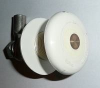 |