|
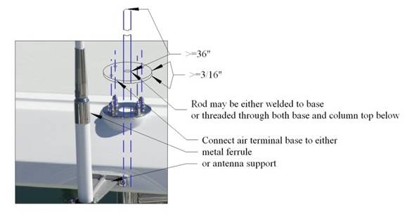
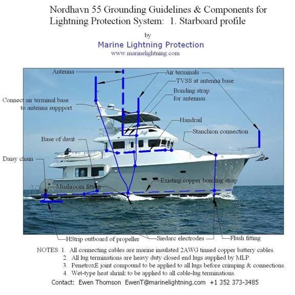
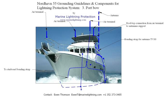
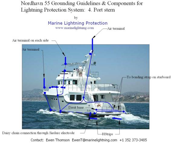
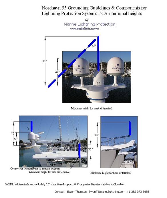
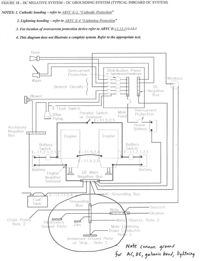
NOTE: While this installation was done on a new Nordhavn, the copper bonding strip installed by Nordhavn for galvanic bonding can also be used as the backbone of a retrofit lightning protection system. See Lone Wolf, a Nordhavn 62. Guidelines for layout, components and installation of lightning protection system on a Nordhavn 551. OverviewThe lightning protection system comprises an interconnected network of air terminals, conductors, and grounding electrodes that form a conducting grid outside the interior space of the vessel. The protective zone provided by the air terminals gives coverage over all deck area and interior space. Since the VHF antennas mounted on the fly bridge are not included in the protective zone, roof top connections are made between each antenna support and the closest air terminal and a transient voltage surge suppressor (TVSS) is connected in each antenna cable. Down conductors are preferentially routed externally to all wiring, plumbing and occupied regions, the exception being the down conductor leading from the air terminal on the centrally-located instrumentation mast. Three continuous loop conductors are incorporated into the network:- (i) the existing stainless steel in the fly bridge superstructure; (ii) the stainless steel railing at main deck level, and: (iii) the existing copper bonding strap about 2' above the waterline. Grounding is provided via six Siedarc electrodes - one on each side at bow, amidships, and stern – and two 0.5 ft2 immersed grounding strips near the stern, one on each side outboard of the propellers. All grounding electrodes are preferentially installed above and near the waterline. Major features are summarized in the diagrams in Appendices 1 to 6. Appendix 7 is a copy of Figure 18 from ABYC Standard E-11 showing a common connection for DC ground, AC ground, cathodic bonding ground, and lightning bonding ground. Appendix 8 gives instructions for lug terminations. 2. Air terminals2.1 MaterialsThe preferred air terminal is constructed from ½" solid copper rod with a rounded tip, tinned to a thickness of at least 0.3 mil. Alternative materials are ½" or thicker stainless steel, aluminum or bronze rods or pipes with a wall thickness of at least 120mil and an area of at least 0.3 in2. 2.2 Bow air terminalIt is recommended that the bow air terminal be attached directly to the top of the bow pulpit, as shown in Appendix 5. The tip height should be 7' above the level of the floor of the bow pulpit. 2.3. Amidships air terminals2.3.1. MountingPresently the fly bridge roof is supported on stainless columns that are secured by means of a stainless ring on top as shown in Figure 2‑1 below. If the stainless ring is replaced by a solid disk of 3/16" or more thickness, then the air terminal can be either welded to this disk or, preferably, screwed through both the disk and into the column flange below. In the latter case the air terminal could be a commercially available ½" tinned copper rod with a ½" -13 threaded base.
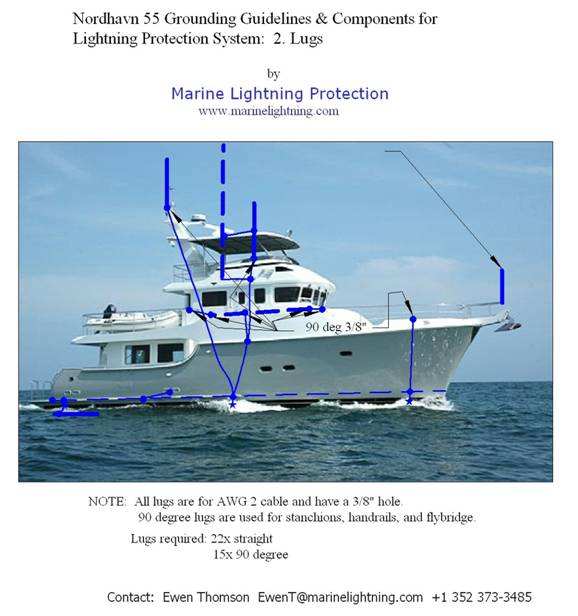
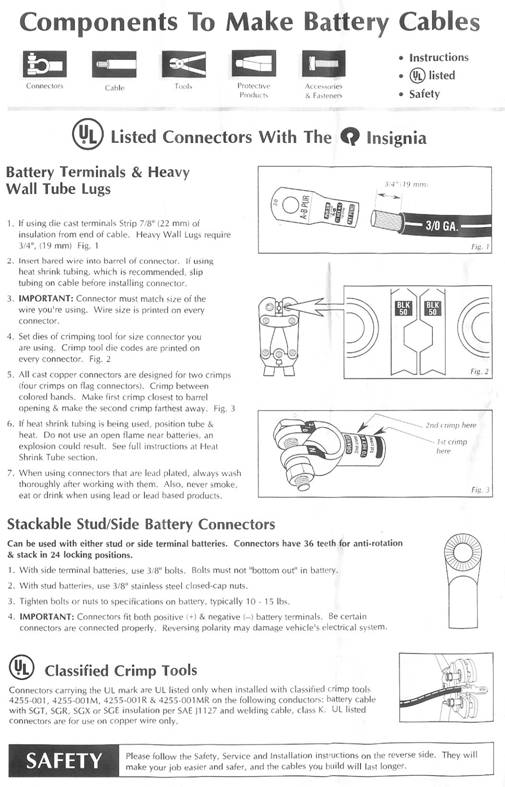
Figure 2 ‑ 1 Air terminal mounting on fly bridge roof 2.3.2. Connection to antennaThe antennas mounted on the side of the fly bridge are not inside the zone of protection and are likely to struck by lightning. This would destroy the antenna and produce a voltage surge on the antenna cable that could damage both the receiver and other onboard electronics. While it is impractical to ensure the survival of the antenna itself, protective measures are highly recommended to reduce the likelihood of damage caused by the voltage surge. As a first precaution, a conducting connection at least equivalent to 2AWG copper (0.04 in2 for copper, 0.25 in2 for stainless steel) should be made between the base of the air terminal and either the metal ferrule on the antenna or the antenna support. Additionally, transient voltage surge suppressors (TVSS) should be installed in the antenna coax as close as possible to the air terminal. These are preferentially mounted on common buses, one on port and one on starboard as close as possible to the point where the cables pass through the coaming. 2.4. Main mast air terminalPresently a lightning dissipator is mounted on a stainless bracket at the top of the main instrumentation mast. Scientific opinion is solidly against the use of these devices. However, its location is an ideal place for a regular air terminal. Appendix 5 shows the recommended height for this. A commercially available 48" or ½" tinned copper rod with blunt tip is sufficiently tall if it includes all mast head electronics within a 90-degree apex cone of protection. Such a rod can be attached by means of ½" -13 nuts above and below the present supporting bracket. In this case a ½" hole should be drilled through the support. 3. Down conductors3.1. RoutingAppendices 1, 3, and 4 show suitable paths for lightning down conductors. All down conductors should be made from insulated 2 AWG tinned copper battery cable terminated with the heavy duty lugs supplied by Marine Lightning Protection (see Section 3.3.1 and Appendix 8 for termination details). In general, the preferred route is the most direct path from air terminal to the closest grounding electrode with all direction changes by means of as smooth a curve (large radius of curvature) as possible.
3.2.
|