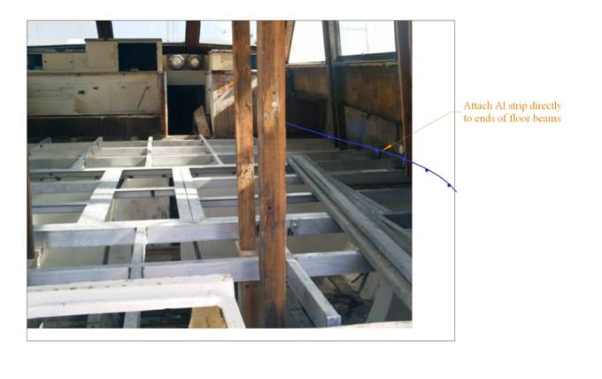
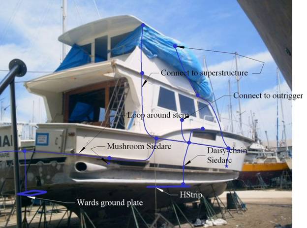
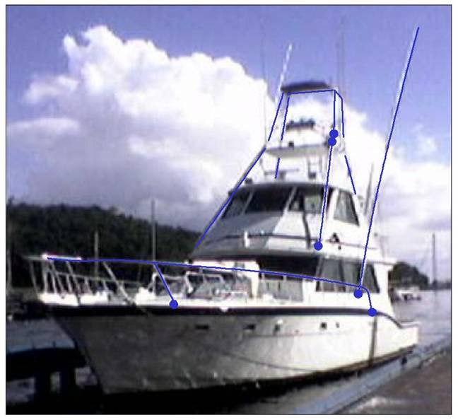
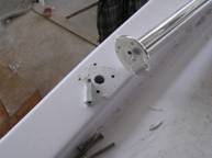
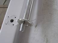
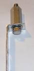
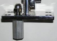
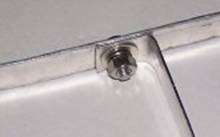
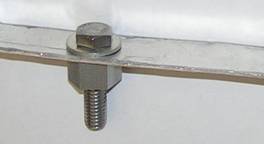
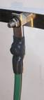
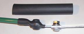
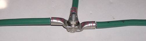
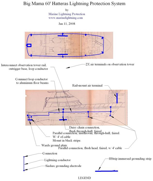
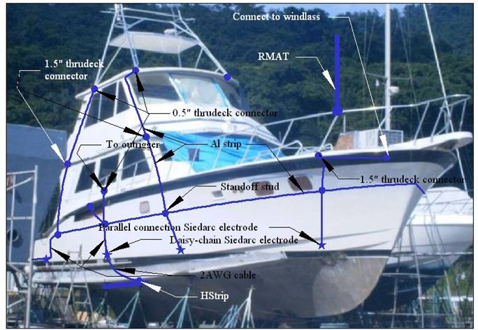
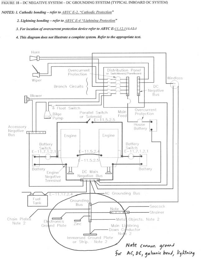
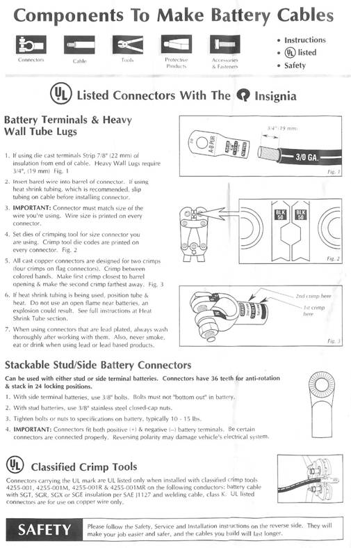
Guidelines for layout, components and installation of lightning protection system on Big Mama 60' Hatteras1. OverviewThe lightning protection system comprises an interconnected network of air terminals, conductors, and grounding electrodes that form a conducting grid outside the interior space of the vessel. The protective zone provided by the air terminals (four rail-mounted air terminals and the two outriggers) gives coverage over all deck area, with the possible exception of a crew member on the bow pulpit, and interior space. Since the VHF antennas are not included in the protective zone, a transient voltage surge suppressor (TVSS) is highly recommended for each antenna cable. This TVSS is not included in the present protection package. Down conductors are preferentially routed externally to all wiring, plumbing and occupied regions. A continuous loop conductor constructed from aluminum strip is connected to the down conductors, the handrail, the metal superstructure, outriggers, aluminum sub flooring, and other large metallic fittings. Grounding is provided via eight Siedarc electrodes, distributed around the hull, two 0.5 ft2 immersed grounding strips near the base of the outriggers, and a Ward's ground plate at the stern. All grounding electrodes are preferentially installed above and near the waterline. Major features are summarized in the diagrams in Appendices 1 and 2. Appendix 3 is a copy of Figure 18 from ABYC Standard E-11 showing a common connection for DC ground, AC ground, cathodic bonding ground, and lightning bonding ground. Appendix 4 gives instructions for lug terminations. 2. Air terminals2.1. MaterialsEach rail-mounted air terminal (RMAT) comprises a 5/8" diameter solid aluminum rod, which is UL listed as a lightning air terminal, fitted into a cast 316 alloy stainless steel ratchet-type rail mount. 2.2. Bow air terminalsIt is recommended that the bow air terminals be attached directly to the top of the bow rail as close to the bow as is practicable. 2.3. Tower air terminals.It is recommended that the tower air terminals be attached directly to the vertical posts such that the top of the air terminal protrudes at least 12" above any fitting on top of the tower. 2.3.1. Connection to antennasAny antenna is at risk of damage even if it is inside the protective zone. While it is impractical to ensure the survival of the antenna itself, protective measures are highly recommended to reduce the likelihood of damage caused by the voltage surge. As a precaution, a transient voltage surge suppressor (TVSS) should be installed in each antenna coax as close as possible to the point where the coax enters inside the lightning protection system. Connect the grounding lug of the TVSS to the closest conductor in the lightning protection system and place at least two tight coils in the coax on the other side of the TVSS. 3. Loop conductor3.1. OverviewThe loop conductor is constructed predominantly from the 1" aluminum strip provided. It encircles the whole boat in a continuous loop as shown in Appendix 1. The most convenient height for this is at the main floor level where it is interconnected with the aluminum flooring beams. 3.2. Floor level loopPass the aluminum strip outside the flooring beams screwing directly into the beams as frequently as practical. See "Connections" below for connection details. Continue this strip forward at the same level to the bow. Figure 3 ‑ 1 Loop around ends of aluminum floor beams 3.3. Aft cockpitIn order to avoid a "U" around the aft cockpit gate, drop the loop level to just below the floor level of the cockpit and continue around the stern. This may be constructed of either aluminum strip or 2AWG insulated battery cable (supplied). If battery cable, use a bimetallic connector for the point between the aluminum strip and the lug, attempting to cover both the lug and aluminum strip connections with the wet type heat shrink provided (see Section 4.4.5 below). Figure 3 ‑ 2 Loop around stern 4. Down conductors4.1. Routing for additional conductorsAppendices 1, 2, and Figure 3‑2 show suitable paths for lightning down conductors. All down conductors should be made from either the 1" aluminum strip provided or insulated 2 AWG tinned copper battery cable terminated with the heavy duty lugs supplied by Marine Lightning Protection (see Appendix 4 for termination details). In general, the preferred route is the most direct path from air terminal to the closest grounding electrode with all direction changes by means of as smooth a curve (large radius of curvature) as possible. However, right angled connections between different conductors is acceptable. 4.2. Use of metallic fittingsThe outriggers, metal handrails, and metal superstructure are used as conductors in the lightning protection system, as shown in Figure 4‑1. Connections should be made at the ends of these fittings as indicated. Appendix 2 shows the interconnections between the lightning protection system components and these fittings. Figure 4 ‑ 1 Metal fittings and connection points for LPS 4.3. Down conductors to electrodes and grounding stripsAll connections to grounding strips and Siedarc electrodes are to be made from 2AWG marine-grade insulated battery cable. This cable is already supplied with any electrodes that have a parallel connection. These cables may be lengthened using either similar cable or aluminum strip connected through the supplied bimetallic connectors. See Section 4.4.5 below for details of this connection between tinned copper and aluminum 4.4. Connections4.4.1. Lug-cableAll lugs are intended for 2AWG cable and have a 3/8" diameter hole. (NOTE: AN exception is the lugs that come attached to the daisy-chain Siedarc electrodes, which have a ¼" hole. These should ONLY be used for connecting cable to the electrode and HStrip in the daisy-chain configuration explained in the Installation Directions for the HStrips.) The manufacturer's directions for connecting cable to lug are included in Appendix 4. For better electrical continuity, 0.1-0.3 ml of PenetroxE joint compound should be injected into each lug before inserting the stripped cable. Also, application of heat shrink (with a 1.5" cable overlap) is highly recommended to improve resilience and further impede moisture intrusion. PenetroxE should also be applied between surfaces that are to be connected before attachment. 4.4.2. Stainless fittingsThere are two ways to make a connection through the deck or topsides to a stainless fitting: a. Threaded hole inside fittingThis method is useful in a stanchion or vertical post where a hole can be made internally. This is demonstrated in the photos below. The fitting is first removed from the deck, a 3/8-16 thread is tapped into the fitting, and a thrudeck connector with threaded stud is screwed into the fitting. Use threadlock to ensure a permanent attachment. Drill a 7/8" diameter hole through the deck or topside wall in line with the connector and insert the connector into this hole when reattaching the fitting. The electrical connection can then be made inside the boat using the 3/8-16 thread inside the connector. Figure 4 ‑ 2 Attachment of thrudeck connector using threaded hole in fitting b. Threaded hole in flangeIn an alternative to a above, the threaded hole can be made through an exposed surface in the same way and capped with an acorn nut, embedded with marine sealant, to ensure a watertight attachment, as shown below. Figure 4 ‑ 3 Attachment of thrudeck connector using external threaded hole c. Though bolt through fitting flangeThis method does not give as good a connection as the above two but may be the only option if the fitting cannot be removed. Basically it is identical to the above except that the hex stud is not used and the through-bolt is either aluminum (e.g. TCA15) or tinned brass (e.g. TC15) . On the inside of the deck the connection is made to a ½" hex stud. 4.4.3. Aluminum strip to aluminum strip Drill a 3/8" hole through the two aluminum strips and through bolt with stainless hardware. Apply Penetrox A between mating surfaces. 4.4.4. Standoff studUse a ½" standoff stud for superior connections to the main loop. Drill a 3/8" diameter hole through the aluminum strip, insert the stainless bolt through the aluminum (1" diameter) washer and the strip, and then screw on the ½" aluminum stud. Connections can then be made using the stainless washer (7/8" diameter), lock washer, and jam nut. If the connecting conductor is copper alloy or tinned copper use a bimetallic connector (see next section). Figure 4 ‑ 4 Aluminum stud mounted on aluminum strip 4.4.5. Aluminum strip to tinned copper lugUse the bimetallic connector (BMC) provided. If the connection is to be made to the loop conductor, connect the bimetallic connector to an aluminum stud attached directly to the loop via a 3/8" hole through the loop strip. If the connection is to be made as a butt connection to an aluminum strip, drill a 3/8" hole about ¾ " from the end of the strip, feed a stainless bolt first through an aluminum washer, then the strip, then the aluminum end of the bimetallic connector, a stainless washer, lock washer and secure with the jam nut. Encase both connecting screws in the heat shrink provided in the BMC package to exclude moisture. Figure 4 ‑ 5 Bimetallic connector connected to standoff stud on loop (left) and aluminum strip extension (right) 4.4.6. Splices between tinned copper cablesSplices between cables can be made by terminating each cable in a lug at the point of the splice, stacking the lugs together and securing with a through bolt and nut. When splicing into a main down conductor, assure that the down conductor lugs are at 180 degrees and the lug on the spliced cable is angled down as much as possible to avoid U-shaped loops. Cover all splices with wet-type heat shrink or waterproof tape. Alternatively, 2- 3- and 4-way splices can be made with S-2A, Splice-3 and Splice-4 respectively. These all come with tinned hardware for galvanic compatibility. Figure 4 ‑ 6 Splice connection using lugs and cable 5. Grounding5.1. Siedarc electrodes in through-hull fittingsElectrode positioning is illustrated in Appendices 1 and 2 and Figure 3‑2 . Two flush-head electrodes with parallel connectors are installed near the bow, and two more below the down conductor at the front of the cabin. Two flush-head electrodes with daisy-chain connections are installed amidships beneath the outriggers. The connection to these is continued to the HStrips on both sides. Two mushroom-head electrodes with parallel connectors are installed where near the stern. See Appendices 1,3,4 and 6. Generally, each electrode should be installed above the stationary waterline and below the lowest flange of any nearby plumbing through hulls. In addition, the two stern electrodes should be positioned so that the cable from the electrode to the HStrip is perpendicular to the strip. Each electrode cable is attached to the bonding loop by the shortest path possible, with the lug at 90 degrees to the bonding strap, and using the same 3/8" machine bolt to attach the electrode cable,and corresponding down conductor to the bonding strap. See Installation Instructions for Siedarc electrodes for details. 5.1. HStrip immersed grounding stripsPlace each HStrip below the waterline at a depth where it will be immersed during all normal modes of operation. The connection from the bonding strap to each HStrip should be made by as direct a path as possible from the strap, through the daisy-chain Siedarc electrode, to one of the HStrip bolts. See Installation Instructions for HStrip grounding strips for details. 5.2. Wards ground plate.Install this below the waterline at the stern as shown, with a splice connection to the aft part of the loop conductor as shown in Figure 4‑6. 6. NoticeThe lightning protection system described in this document is fundamentally consistent with Chapter 8 in the National Fire Protection Association Standard NFPA780-2008. Any departures are considered by the author to be improvements over this revised standard. In general, lightning protection systems are limited by the current state of knowledge and no implication is intended that this, or any, protection system will prevent damage or injury. 7. AppendicesAppendix 1 Appendix 2 Appendix 3 Figure 18 from ABYC E-11 2003 Appendix 4 Termination directions for heavy duty lugs |
Contact
Marine Lightning Protection Inc.3215 NW 17th StreetGainesville Florida 32605 |
 |
Phone: +1 352 373-3485
Email: info@marinelightning.com URL: www.marinelightning.com
|
|