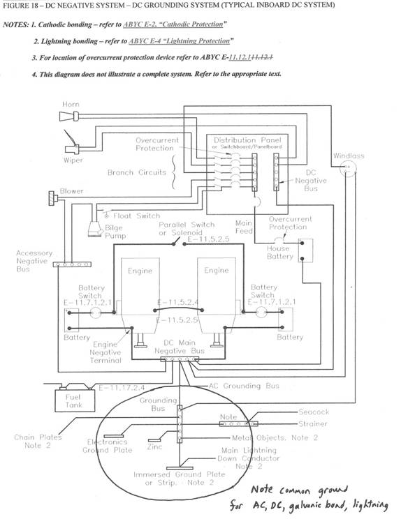
Guidelines for layout, components and installation of lightning protection system on Outbound 461. OverviewThe lightning protection system comprises an interconnected network of air terminals, conductors, and grounding electrodes that form a conducting grid outside the interior space of the vessel. The protective zone provided by the air terminal at masthead and stainless rigging gives coverage over all deck area,. Since the VHF antenna may not be included in the protective zone, a transient voltage surge suppressor (TVSS) is highly recommended for the antenna cable. This TVSS is not included in the present protection package. Down conductors are preferentially routed externally to all wiring, plumbing and occupied regions. A continuous loop conductor constructed mainly from the aluminum toe rail is connected to the down conductors, mast, and other large metallic fittings. Grounding is provided via six Siedarc electrodes, distributed around the hull, and two 0.5 ft2 immersed grounding strips near the chainplates. All grounding electrodes are preferentially installed above and near the waterline.Appendix 1 is a copy of Figure 18 from ABYC Standard E-11 showing a common connection for DC ground, AC ground, cathodic bonding ground, and lightning bonding ground. Appendix 2 gives instructions for lug terminations. 2. Air terminals2.1. MaterialsThe masthead air terminal comprises a 1/2" diameter solid aluminum rod with a 1" length of ½ - 13 thread.2.2. PlacementIt is recommended that the air terminal be attached directly to the top of the masthead such that all sensors are within a cone of protection with a 90 degree apex angle.2.3. Attachment.Attach the air terminal to the mast head such that it is securely mounted and in contact with the mast.2.4 TVSS for antennasAny antenna is at risk of damage even if it is inside the protective zone. While it is impractical to ensure the survival of the antenna itself, protective measures are highly recommended to reduce the likelihood of damage caused by the voltage surge. As a precaution, a transient voltage surge suppressor (TVSS) should be installed in each antenna coax as close as possible to the point where the leaves the mast. Connect the grounding lug of the TVSS to either the mast or the closest conductor in the lightning protection system and place at least two tight coils in the coax on the other side of the TVSS.3. Loop conductorThe loop conductor is constructed predominantly from the aluminum toe rail. The loop encircles the whole boat in a continuous loop as shown in Figure 3‑1. Continuity is provided across any breaks using the 1" aluminum strip and stanchion connectors provided. Connections are described in section 5 below. . If possible, encapsulate the aluminum strip in fiberglass, especially for the bow and stern connections, to minimize the risk of corrosion. Also, ensure that any stainless steel hardware that is in contact with any aluminum part is coated with moisture repellant.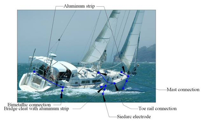
Figure 3‑1 Loop condutor layout 4. Main conductors4.1. Mast-to-rail connectionThe 1" aluminum strip provided is used to connect the mast to the toe rail via the mast connector and rail connector as shown in Figure 3.1. This connection is made inside the boat.4.2. Rail-to-electrode cable connectionA short piece of the 1" aluminum strip (CAlS)is also used to connect the rail to the bimetallic connector (BMC) that provides an encapsulated joint to the tinned copper insulated cable attached to each electrode.4.3. Conductors to electrodes and grounding stripsAll connections to grounding strips and Siedarc electrodes are to be made from 2AWG marine-grade insulated battery cable. This cable is already supplied with the four electrodes that have a perpendicular connection (the fore and aft electrodes). The amidships electrodes employ a daisy-chain connection to the HStrips as explained in Section 6. Additional 2AWG tinned copper battey cable is required for these. The various connections for the bow electrode is shown for in Figure 4‑1.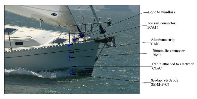
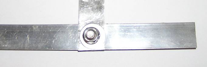
Figure 4‑1 Bow connections from rail to electrode 5. Connections.5.1.1. Toe rail to aluminum stripa. Insertion through toe railEach connection to the toe rail uses the TCA30 toe rail connector kit provided. To connect to the toe rail, drill a 5/16 " hole through the rail and the deck and tap a 3/8-16 thread using the tap provided. Unscrew the stainless jam nut, washers and ½" aluminum nut from the bottom of the connector and, leaving the top aluminum washer on the connector, screw it partially into the threaded hole. When about ½" from the top, apply a small bead of Penetrox A (grey color) to the remaining thread and both sides of washer. Screw in, remove excess Penetrox A using solvent, and weather seal around both acorn nut and aluminum washer with marine sealant such as 3m 5200. From below the deck, place the aluminum washer over the exposed thread and screw on the ½" aluminum nut.b. Connection to stripThe amidships cleats and the ends of the toe rails forward and aft are bridged with a piece of aluminum strip. For these connections, after cutting the strip to the appropriate length, drill a 3/8" hole centered 5/8" from each end of the strip so that the holes are correctly aligned with the mating bolt protruding from the toe rail connector.. After applying Penetrox A to each mating surface, place the strip, aluminum washer then split washer over the exposed thread and screw on the jam nut to secure.c. Connection to electrodeNote that all electrode should be installed before this connection can be made. Cut a piece of aluminum strip to the appropriate length (as explained in 5.1.5), drill a 3/8" hole centered 5/8" from the end of the strip and bend the last 1 ¼" into a right-angle corner. Place the strip, aluminum washer then split washer over the exposed thread and screw on the jam nut to secure.5.1.2. Mast to aluminum strip at ceiling levelThis connection is made at ceiling level on each side of the mast using the MC-A connector supplied. Mount to the mast by following the detailed instructionsinstallation instructions provided. Cut a piece of aluminum strip to length to join the mast connector to the rail connector and install in the same way as described in 5.1.1b. Note that the mast connector is installed with the vertical leg pointing up the mast.5.1.3. Mast to cable at floor levelThis connection is made at floor level on each side of the mast using theMC-Cconnector supplied. Mount to the mast by following the detailed instructions in the installation instructions provided. Cut a piece of aluminum strip to length to join the mast connector to the rail connector and install in the same way as described in 5.1.1b. Note that the mast connector is installed with the vertical leg pointing up the mast.5.1.4. Aluminum strip to aluminum stripDrill a 3/8" hole through the two aluminum strips and through bolt with stainless hardware adding aluminum washers on each side of the strips. Apply Penetrox A between mating surfaces before securing. See Figure 5‑1 Connection between aluminum strips..
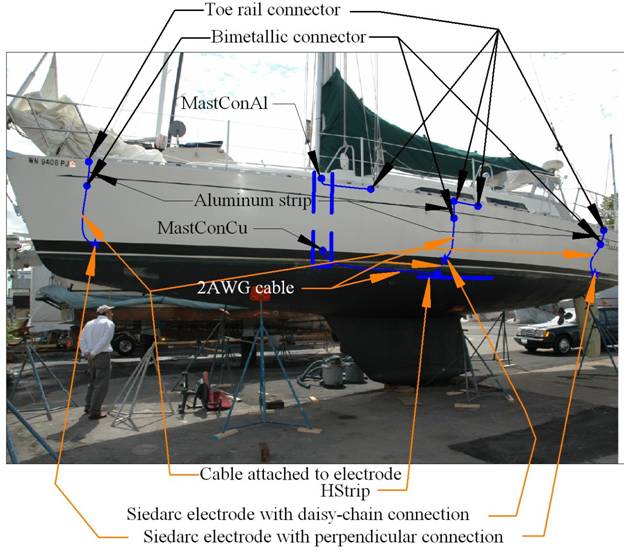
Figure 5‑1 Connection between aluminum strips 5.1.5. Bimetallic connection to electrode cableThe connection to each electrode is made from the cable supplied with the electrode, through the bimetallic connector, to a strip attached to the through-rail connection. After installing the electrode as described in 6.2, strip ¾" of insulation off the end of the cable and crimp onto the lug-end of the bimetallic connector. (See Appendix 2) Then cut a piece of aluminum strip of the appropriate length, allowing an extra 1 ¼" for the connection to the rail connector. Drill two holes in this strip, each one 5/8" from each end. Through-bolt one end to the bimetallic connector, apply the heat shrink tubing to cover both bolts, and then follow the instructions in 4.2 for the attachment of the other end to the through-rail connector.5.1.6. Bonding connection from aluminum strip to stainless fittingThe windlass or bow roller should be connected to the bow strip shown in Figure 4‑1 Bow connections from rail to electrodeusing another piece of aluminum strip. Add an aluminum washer at each stainless/strip joint and apply Penetrox A before securing. Repeat for other bonding connections to large metallic fittings such as chainplates, handrails, bow and stern pulpits, bimini, etc.6. Grounding6.1. OverviewElectrode positioning is illustrated in Figure 6‑1. Two flush-head electrodes with perpendicular connections to integrated cable are installed near the bow, and two more at the stern. Two flush-head electrodes with daisy-chain connections are installed amidships. The connection to these is continued to the HStrips on both sides. Generally, each electrode should be installed above the stationary waterline and below the lowest flange of any nearby metallic plumbing through hulls. In addition, the two amidships electrodes and the HStrips should be positioned so that the cable from the electrode to the HStrip is perpendicular to the HStrip.
Figure 6‑1 Layout for grounding strips and electrodes 6.2. Siedarc electrodes in through-hull fittings6.2.1. Forward and aft electrodes with attached cableThese electrodes are supplied with 4' of 2AWG cable already swaged to the electrode. Place the electrodes directly below the corresponding rail connection following the directions explained in the installation guide. Route the cable in a gentle curve from the electrode to beneath the rail connector and then bridge the gap with a piece of aluminum strip as explained in 5.1.1c.6.2.2. Amidships electrodes with daisy-chain connectionsAll connections below the bimetallic connector are made from 2AWG insulated battery cable, using wet-type heat shrink wherever possible The amidships electrodes use a daisy-chain connection. One piece of cable is crimped at one end to the bimetallic connector, and the other to the lug provided with the electrode that screws into the electrode via a ¼" screw. A second piece of cable is crimped at one end to the second lug provided with the electrode, that also is screwed onto the electrode, and the other end is crimped to one of the lugs provided with the HStrip hardware. A third piece of cable is crimped at one end to the other lug provided with the HStrip and at the other end to the MastCon Cu mast connector. Complete the connection to both the HStrip and the mast as shown in Figure 6‑1. Also see Section 2.1.1 in the installation instructions for Siedarc electrodes.6.3. HStrip immersed grounding stripsSee Figure 6‑1 for the port layout of the cables connected to the HStrips. Note that the layout is mirrored on the starboard side. The HStrip installation instructions give detailed directions for installation of the HStrips. Place each HStrip below the waterline at a depth where it will be immersed during all normal modes of operation. Exact placement is not crucial. The connection from the toe rail to each HStrip should be made by as direct a path as possible through the aluminum strip, to the bimetallic connector, to the daisy-chain Siedarc electrode, to the longer of the HStrip bolts, and finally to the MastConCu mast connector just below floor level as explained in 6.2.2. .7. NoticeThe lightning protection system described in this document is fundamentally consistent with Chapter 8 in the National Fire Protection Association Standard NFPA780-2008. Any departures are considered to be improvements over this revised standard or reasonable compromises. In general, lightning protection systems are limited by the current state of knowledge and no implication is intended that this, or any, protection system will prevent damage or injury.8. AppendicesAppendix 1 Figure 18 from ABYC E-11 2003
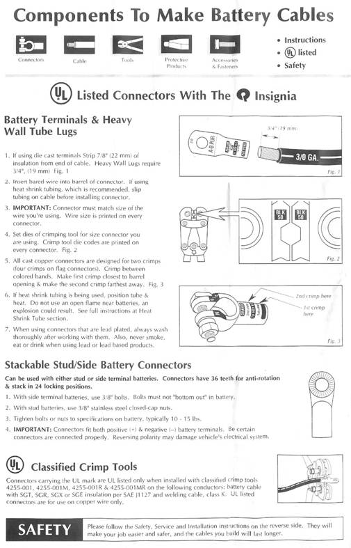
Appendix 2 Termination directions for heavy duty lugs
|
Contact
Marine Lightning Protection Inc.3215 NW 17th StreetGainesville Florida 32605 |
 |
Phone: +1 352 373-3485
Email: info@marinelightning.com URL: www.marinelightning.com
|
|
Please call or email if you have any questions.